Wrapping machine and top foil wrapping machine

a wrapping machine and foil technology, applied in the field of wrapping machines, can solve the problems of inability to guarantee the functionality of the machine, poor work safety, and disassembly of the prior, and achieve the effect of small freight costs and easy and quick re-operation

Active Publication Date: 2006-05-02
M HALOILA
View PDF11 Cites 24 Cited by
  • Summary
  • Abstract
  • Description
  • Claims
  • Application Information

AI Technical Summary

Benefits of technology

[0009]A specific object of the invention is to disclose a wrapping machine and / or top foil wrapping machine that, for transportation and storage, has a packaged size smaller than that of earlier machines and for which the freight costs are small.
[0010]A further object of the invention is to disclose a wrapping machine and / or top foil wrapping machine that can be easily and quickly put into working order at the place of use without requiring the person doing the work to have special tools or special skills.

Problems solved by technology

A problem with the prior-art wrapping machine and / or top foil wrapping machine is that it has to be transported from the place of manufacture to the place of use for the client in full size, in other words, with a height dimension that the machine will have when used at the place of application.
To reduce the packaged size of the machine for transportation, disassembly of the prior-art machine is out of the question because assembling it requires a great deal of work, time, expertise and the use of special tools, while the functionality of the machine can not be guaranteed if there is no skilled personnel and special tools available for the assembly work.
As numerous parts are located at a level high up from the floor, work safety is also poor because the person performing the installation has to work standing on ladders and similar levels elevated from the floor level.
On the other hand, transportation of a full-size machine involves high freight costs, impairing profitability.

Method used


Image

  • Wrapping machine and top foil wrapping machine
  • Wrapping machine and top foil wrapping machine
  • Wrapping machine and top foil wrapping machine

Examples


Embodiment Construction

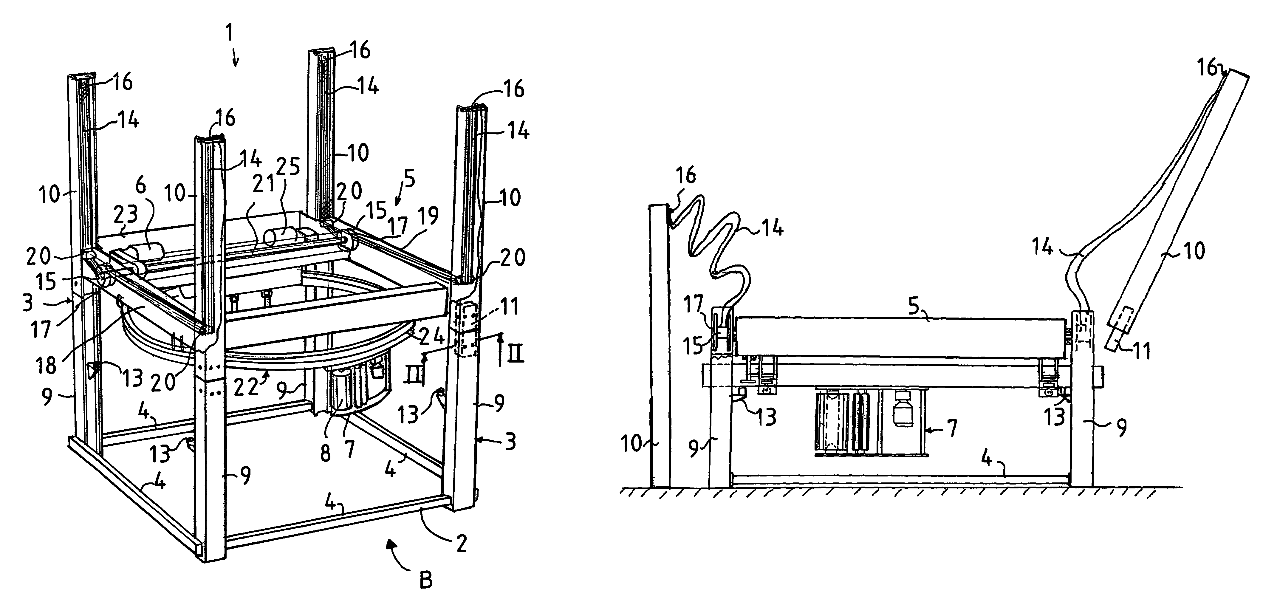
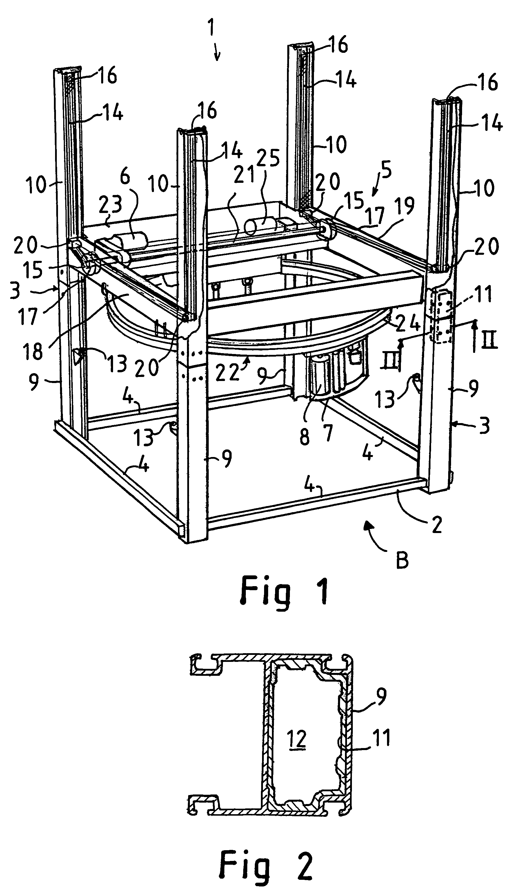
[0028]FIG. 1 presents a wrapping machine 1 for wrapping a plastic foil web around an object (not shown) to be packaged. The wrapping machine 1 comprises a machine frame 2 supported on a fixed floor base. The machine frame 2 comprises four upright vertical columns 3 arranged at a distance from each other in a rectangular configuration such that a vertical column 3 is placed at each corner of the imaginary rectangular configuration. A lifting frame 5 has been arranged to be vertically movable along the vertical columns 3 by means of a lifting motor 6. From the lifting motor 6, power is transmitted by power transmission means to produce a vertical motion of the lifting frame 5. The power transmission means comprise flexible flat belts 14 and pulleys 15 for transmitting the power of the lifting motor 6 to the flat belts 14.

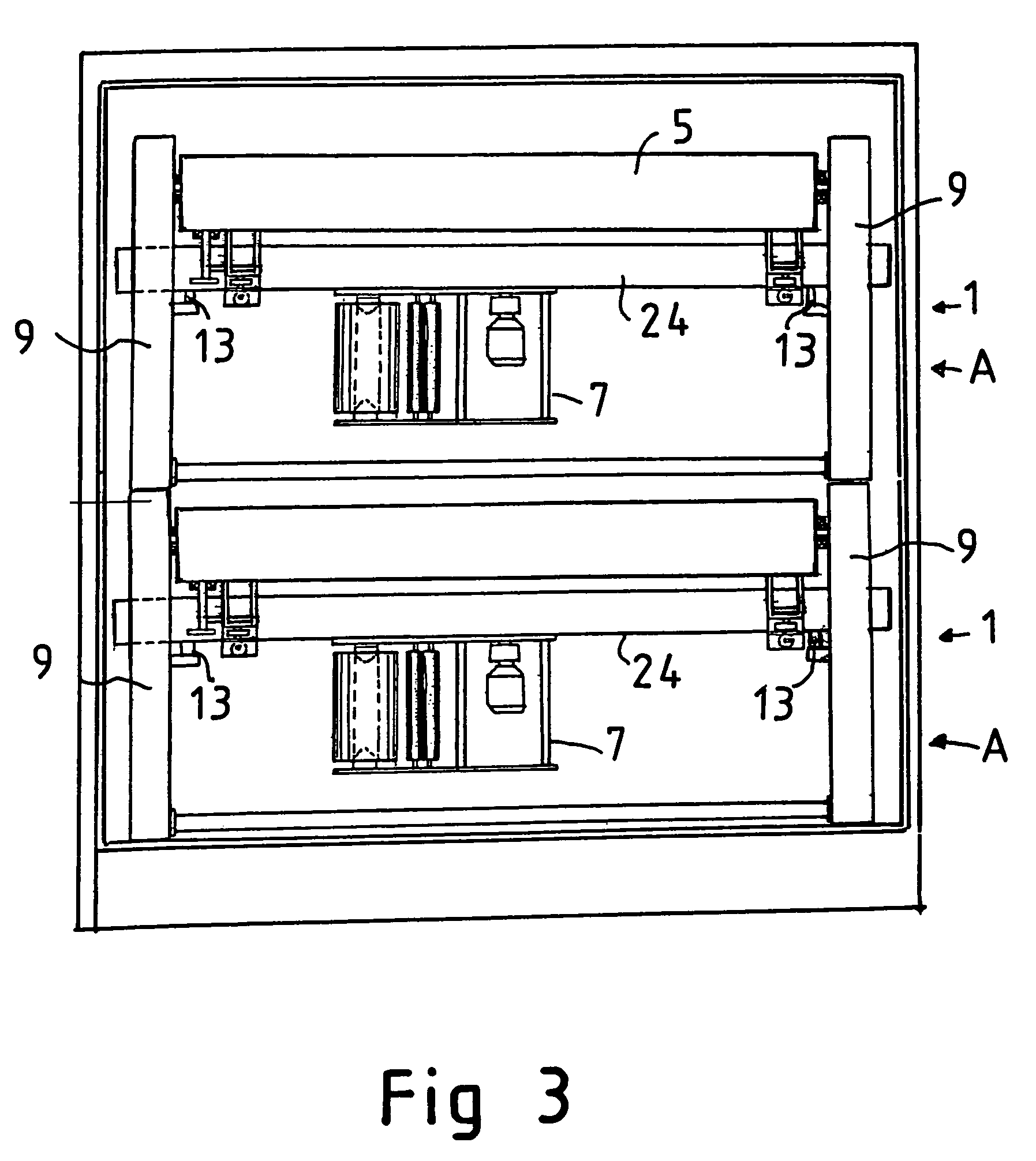
[0029]A foil dispenser 7, on which a foil web roll can be rotatably supported, has been arranged to circulate as guided by a circular ring arrangement 22 along a circ...


PUM

PropertyMeasurementUnit
flexibleaaaaaaaaaa
lengthaaaaaaaaaa
poweraaaaaaaaaa

Abstract

A wrapping machine and/or a top foil wrapping machine machine frame, which is supported on a fixed base and has upright vertical columns and horizontal cross members connecting the vertical columns to each other. Each vertical column has at least two column parts detachably joined together end on end, the column parts including a lower column part and an upper column part. Only the lower column parts of the vertical columns are connected to each other by the cross members while the upper column parts are not connected to each other. To store and/or transport the machine, the machine is reduced to a low size (A) for packaging, by detaching the upper column parts from the lower column parts of the vertical columns. The upper column parts may be reattached to the lower column parts to install the machine from the packaged size (A) to a full working size (B).

Description

FIELD OF THE INVENTION[0001]The present invention relates to a wrapping machine, and more particularly, to a top foil wrapping machine.BACKGROUND OF THE INVENTION[0002]In prior art, a wrapping machine used to wrap a plastic foil web around an object to be wrapped is known. Similarly, a top foil wrapping machine used to set a desired length of top foil onto an object to be wrapped is known.[0003]The object to be wrapped is usually a load placed on a pallet, which typically is an assembly of the form of a rectangular parallelepiped. A feature common to the wrapping machine and the top foil wrapping machine is that they comprise a machine frame supported on a fixed floor base. The frame usually comprises four upright vertical columns. The upper ends of the vertical columns are connected to each other by cross members forming a so-called top frame, while their lower ends are similarly connected together by cross members. Both machines further comprise a lifting frame arranged to be vert...

Claims


Application Information

Patent Timeline
Patent Type & Authority Patents(United States)
IPC IPC(8): B65B59/04B65B45/00B65B11/02F16H19/02
CPCB65B11/025B65B2210/18B65B45/00
Inventor SUOLAHTI, YRJO
Owner M HALOILA
Why Eureka
Try Eureka