

Rechargeable pneumatic power supply
- Summary
- Abstract
- Description
- Claims
- Application Information
AI Technical Summary
Benefits of technology
Problems solved by technology
Method used
Image

Examples
Embodiment Construction
[0026]While the invention is susceptible to embodiments in many different forms, there are shown in the drawings and will be described herein, in detail, the preferred embodiments of the present invention. It should be understood, however, that the present disclosure is to be considered an exemplification of the principles of the invention and is not intended to limit the spirit or scope of the invention and / or claims of the embodiments illustrated.
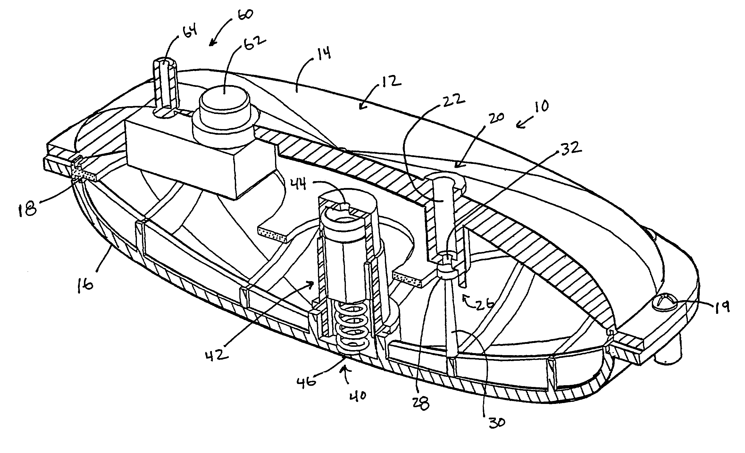
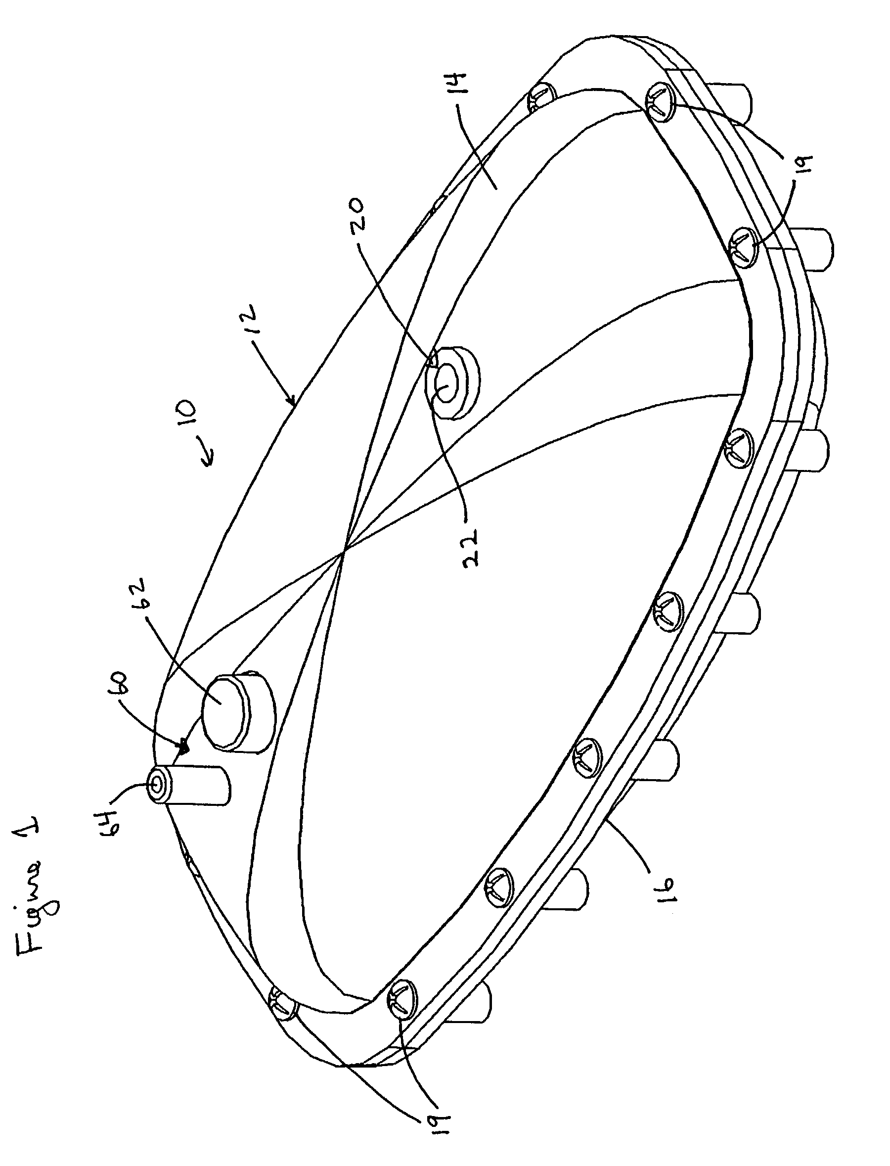
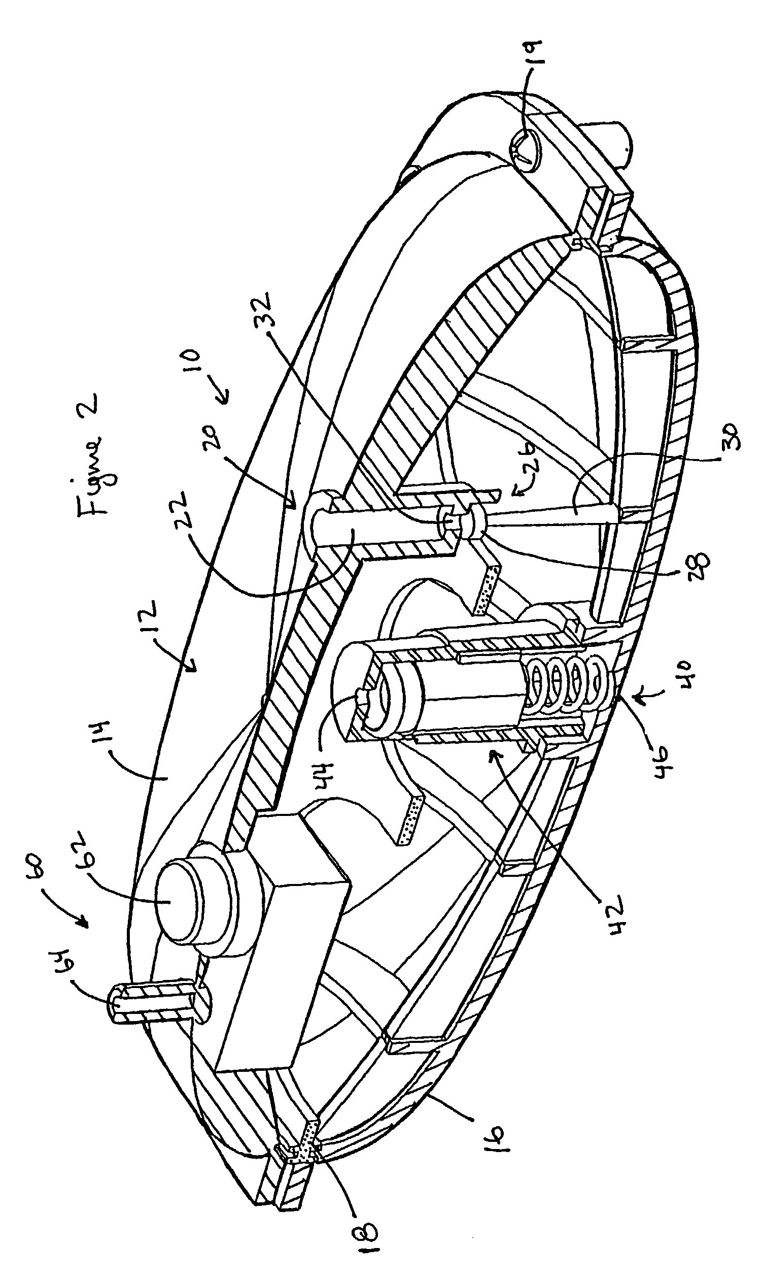
[0027]As mentioned above, the present invention relates to pneumatically operated devices and is used in a wide variety of applications. A pneumatically operated device utilizes a compressed fluid to operate a pneumatic motor or mechanism that drives or operates the device. While some devices are tethered to an external source of compressed fluid, other devices include an on-board refillable reservoir that the user may refill with compressed fluid. The means to continuously refill the reservoir with compressed fluid may be accomplished by...
PUM
 Abstract
Description
Claims
Application Information