Cryogenic tank for storing cryogenic fuel in a motor vehicle and method for using same

a technology for cryogenic fuel and motor vehicles, which is applied in the direction of container discharging methods, vessel construction details, lighting and heating apparatus, etc., can solve the problems of significant scale, undesired heat feeding to stored fuel on a significant scale, and hysteresis behavior, etc., to achieve low thermal capacity, small size, and low cost

Inactive Publication Date: 2006-05-02
BMW SUPPLIER NO 141 642 10
View PDF15 Cites 6 Cited by
  • Summary
  • Abstract
  • Description
  • Claims
  • Application Information

AI Technical Summary

Benefits of technology

[0010]As long as the receiving element and the output element are separated from each other and thus are not connected together so as to conduct or transfer heat, there is certainly no thermal input of virtually any kind (with the exception of thermal radiation) over this thermal bridge element into the cryo tank or any supply of heat to the fuel stored therein. In particular, then heat cannot be supplied over lines, which are, in fact, blocked, but, nevertheless, lead into the storage space of the internal container, to the fuel therein. The aforementioned continuous heat input, which may in deed be low, but still not ignorable, into the cryo tank over special lines, provided specifically to supply heat to the cryo tank, cannot take place, if such a targeted supply of heat is not desired. Not until and only as long as this thermal bridge element is closed, does such a targeted heat input into the system occur, as desired. If thereafter the thermal bridge element is opened, the supply of heat is stopped almost suddenly, in particular if the receiving element, assigned to the internal container, has a relatively low thermal capacity. In this sense the so-called receiving element of the internal container can have a lower thermal capacity and / or a smaller size than the output element, assigned to the external container.
[0011]Like a relay, the switch selectable thermal bridge element can be changed over electromagnetically. A related electric line to supply the switch selectable electromagnet has to lead only to the so-called output element, which is provided on the external container, but not to the so-called receiving element, which is provided on the internal container, so that the desired effect, namely no thermal bridge in the form of a continuous electric line, is still guaranteed.
[0012]Whereas in the opened state of this thermal bridge element, there is, as desired, no heat input of any kind into the system or into the fuel stored therein, when the thermal bridge element is closed, an optimal supply of heat to the cryo fuel stored in the internal container is desired. To achieve this state, the switch selectable thermal bridge element can be designed in such a manner that in the closed state a spatial (and not just linear) contact area or the heat transfer area is formed between the receiving element and the output element of the switch selectable thermal bridge element. For example, in the so-called closed state of the thermal bridge element a conical pin or the like of the output element can project into a corresponding receptacle of the receiving element and in so doing come to lie as completely as possible against the corresponding receiving wall.

Problems solved by technology

Even if in these known systems no heat input is supposed to occur in the internal storage container, the said lines act as an already existing thermal bridge, over which a small, but not ignorable quantity of heat can get to the stored fuel, a state that is fundamentally undesired.
Another drawback of these known systems lies in their hysteresis behavior, in particular when turning off.
That is, after the targeted thermal input is turned off, heat is fed on a significant scale in an undesired manner to the stored fuel for a certain period of time.
In particular, then heat cannot be supplied over lines, which are, in fact, blocked, but, nevertheless, lead into the storage space of the internal container, to the fuel therein.
The aforementioned continuous heat input, which may in deed be low, but still not ignorable, into the cryo tank over special lines, provided specifically to supply heat to the cryo tank, cannot take place, if such a targeted supply of heat is not desired.

Method used


Image

  • Cryogenic tank for storing cryogenic fuel in a motor vehicle and method for using same
  • Cryogenic tank for storing cryogenic fuel in a motor vehicle and method for using same

Examples


Embodiment Construction

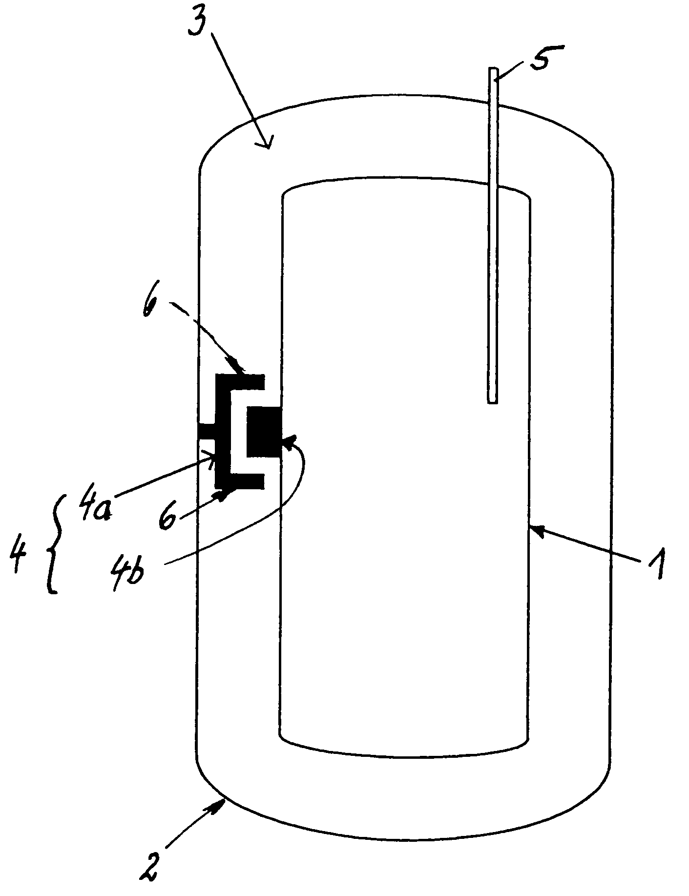
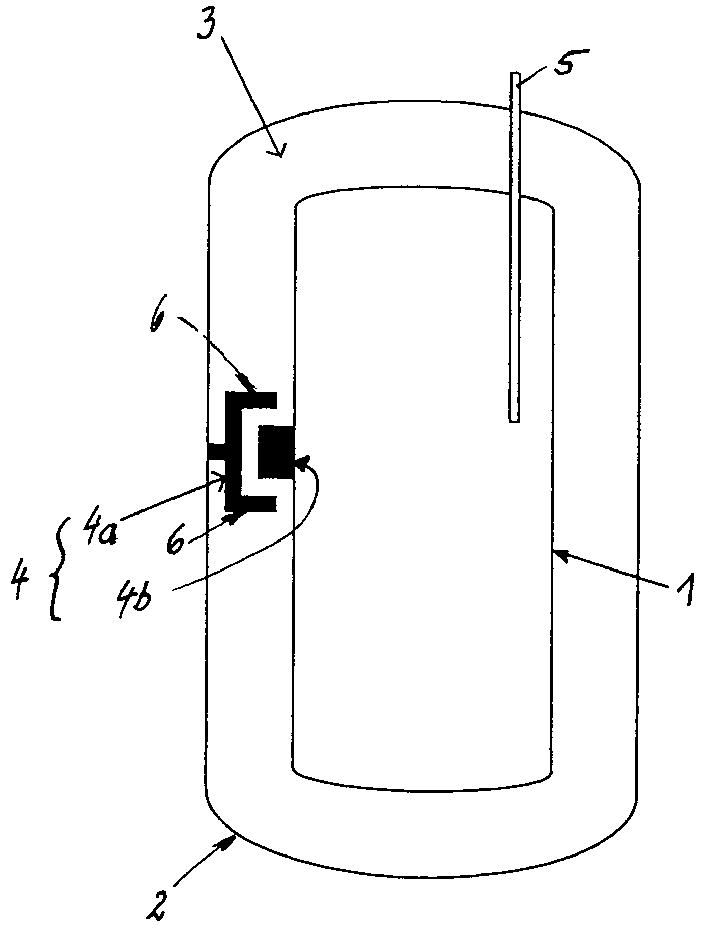
[0016]The reference numeral 1 refers to the internal container of a motor vehicle cryo tank, in which is mostly stored cryo fuel in the liquid state, to supply an internal combustion engine or the like that drives the motor vehicle. This internal container 1 is enveloped by an external container 2, which is spaced apart from said internal container, so that the space 3 between these two containers 1, 2 is largely evacuated. That is, between the wall of the internal container 1 and the wall of the external container 2 there is a so-called insulating vacuum (for this purpose the reference numeral 3 is also used).

[0017]A fuel line 5 is run into the interior of the internal container 1 or out of said internal container through the wall of the external container 2 to the outside; through said fuel line the cryo fuel is conveyed into the internal container 1 or the fuel can be removed from said internal container to supply the said internal combustion engine. The latter occurs with fuel t...


PUM


Abstract

A tank for storing a cryo fuel in a vehicle with an internal storage container, an external container enveloping the internal container, and an electromagnetically switch selectable thermal bridge element which can produce or interrupt a heat conducting connection between the wall of the internal container and the wall of the external container. The thermal bridge element may be designed such that in the closed state a spatial contact area is formed between a receiving element of the thermal switch affixed to the internal container and an output element of the thermal switch affixed to the outer container. The receiving element may have a smaller thermal capacity and/or size than the output element. Either the thermal bridge or a second thermal bridge element may be adapted to cool the internal container.

Description

[0001]The present application is a continuation of International Patent Application No. PCT / EP02 / 08445, filed Jul. 30, 2002, designating the United States of America and published in German as WO 03 / 018344 A1, the entire disclosure of which is incorporated herein by reference. Priority is claimed based on Federal Republic of Germany patent document DE 101 41 048.4 filed Aug. 22, 2001.BACKGROUND AND SUMMARY OF THE INVENTION[0002]The invention relates to a vehicle cryo tank for storing a cryo fuel in a motor vehicle, comprising an internal storage container and an external container, enveloping said internal container, so as to form an insulating vacuum, whereby heat input from the outside into or at the internal container can be switched on or off. The invention further relates to a method for using the same. For the technical environment reference is made to DE 195 46 618 C2 as an example.[0003]Searching for alternative drive energies for motor vehicles, one is also working with liq...

Claims


Application Information

Patent Timeline
Patent Type & Authority Patents(United States)
IPC IPC(8): F17C13/08F17C1/00F17C13/00F28F27/00B60K15/03F17C3/00F17C13/02
CPCF17C3/00F17C13/025F17C13/026F17C13/005Y02E60/321F17C2201/0109F17C2201/056F17C2203/0391F17C2203/0604F17C2203/0607F17C2203/0629F17C2203/0636F17C2205/0323F17C2221/012F17C2221/033F17C2223/0161F17C2223/035F17C2223/043F17C2225/0123F17C2227/0302F17C2227/0337F17C2227/0379F17C2227/0381F17C2227/0383F17C2260/031F17C2260/032F17C2260/033F17C2265/05F17C2270/0168Y02E60/32
Inventor SCHNAGL, JOHANN
Owner BMW SUPPLIER NO 141 642 10
Why Eureka
Try Eureka