Thermal detector, thermal detector device, electronic instrument, and method of manufacturing thermal detector

a technology of thermal detector and support member, which is applied in the direction of optical radiation measurement, instruments, coatings, etc., can solve the problems of high temperature, high temperature, and high temperature of the support member, and achieve the effect of reducing the thermal capacity of the support member

Inactive Publication Date: 2011-07-28
SEIKO EPSON CORP
View PDF23 Cites 29 Cited by
  • Summary
  • Abstract
  • Description
  • Claims
  • Application Information

AI Technical Summary

Benefits of technology

[0041]According to at least one aspect of the present invention as set forth above, it is possible to concomitantly reduce the thermal capacity of a support member for supporting a thermal detector element, while ensuring the mechanical strength needed in the manufacturing process, for example.

Problems solved by technology

The mechanical strength of the support member affects, for example, the frequency of defects (the yield) in the process of manufacturing three-dimensional structures.
For example, flexion and the like may arise in the support member due to the weight of the thermal type light absorbing element, and if the maximum distance separating the support member and the substrate is smaller than the design value, in the event that, for example, wet etching is used in order to form a cavity for thermal separation purposes, sticking (adhesion (bonding) of the substrate and the support member is prone to occur.
Consequently, sticking may be inhibited during the drying process in a wet etching step, for example.

Method used


Image

  • Thermal detector, thermal detector device, electronic instrument, and method of manufacturing thermal detector
  • Thermal detector, thermal detector device, electronic instrument, and method of manufacturing thermal detector
  • Thermal detector, thermal detector device, electronic instrument, and method of manufacturing thermal detector

Examples


first embodiment

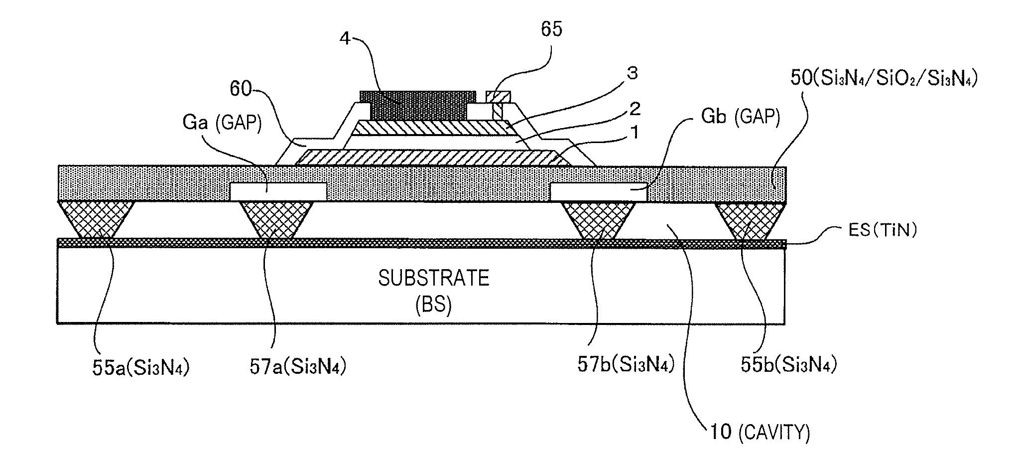
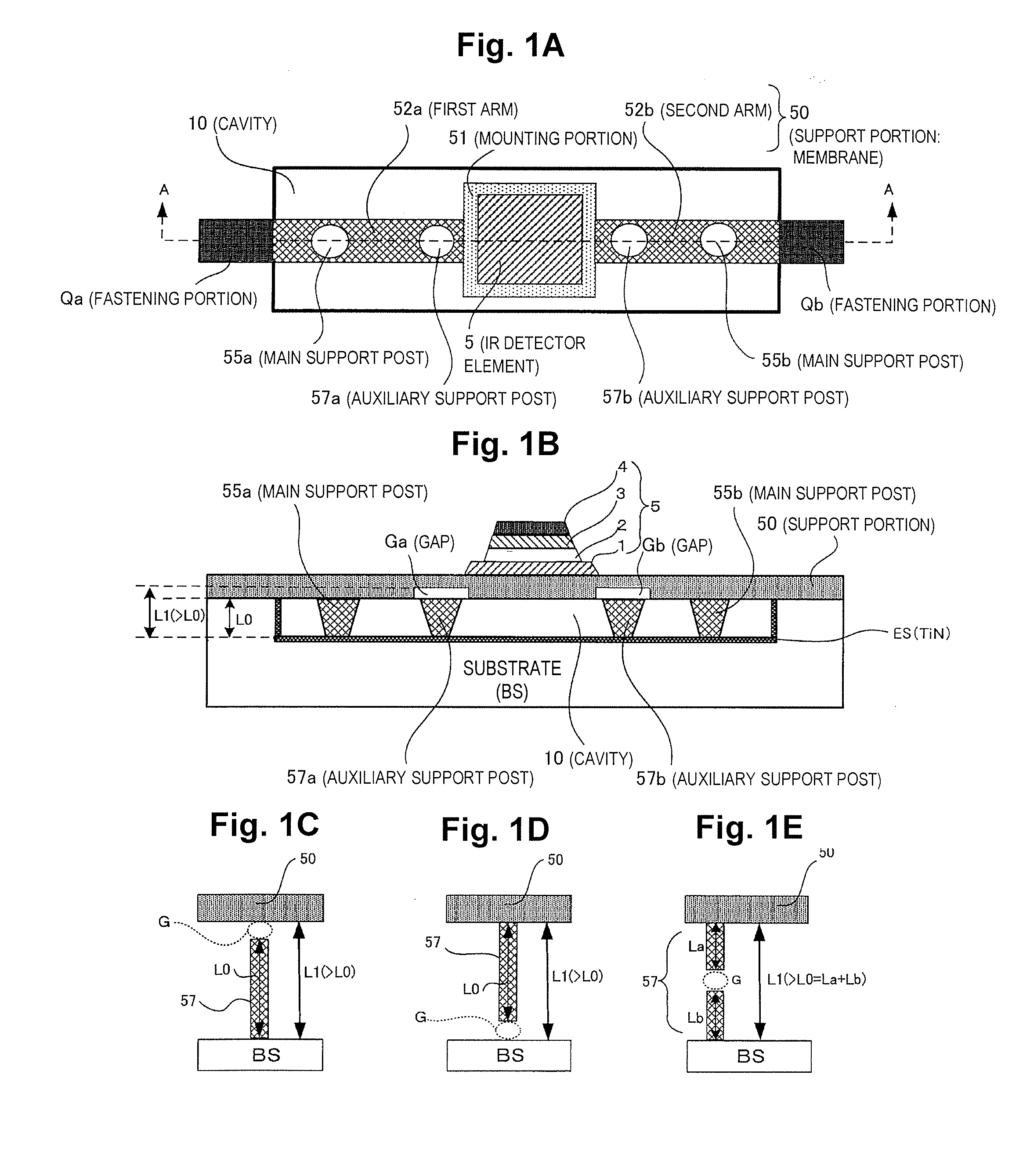
[0054]FIG. 1A to FIG. 1E are drawings illustrating a configuration of an example of a thermal detector (here, a pyroelectric type infrared detector) having auxiliary support posts. FIG. 1A is a plan view of principal portions of the thermal detector; FIG. 1B is a cross-sectional view taken along line A-A in FIG. 1A; and FIG. 1C to FIG. 1E are respectively drawings showing configuration examples of auxiliary support posts.

[0055]The thermal detector shown in FIG. 1A and FIG. 1B is a pyroelectric type infrared detector (pyroelectric type infrared sensor) having a three-dimensional structure formed on a substrate using MEMS (Micro-Electrical-Mechanical Systems) technology (a semiconductor manufacturing technology).

Pyroelectric Type Photodetector Configuration Example

[0056]As shown in FIG. 1A and FIG. 1B, a cavity 10 is provided between the substrate BS and the support member 50. The cavity 10 has a function, for example, of thermally separating the substrate BS from portions of the supp...

second embodiment

[0088]The present embodiment describes an example of preferred placement of auxiliary support posts (and main support posts). FIG. 6A and FIG. 6B are drawings illustrating an example of preferred placement of auxiliary support posts (and main support posts). In FIG. 6A and FIG. 6B, sections common to previous drawings are assigned like reference symbols.

[0089]If a structure whereby support posts are simply provided to support the support member 50 is adopted, during the manufacturing process, there is a possibility that the support posts will act as heat dissipation pathways, and therefore it is necessary for the support posts to be situated at locations away from the thermal detector element. Therefore, in the example of FIG. 6A, the main support posts 55a, 55b are situated large distances away from the thermal detector element 5. Specifically, the main support post 55a is disposed to the substrate side of the first arm 52a, and the main support post 55b is disposed to the substrat...

third embodiment

[0102]FIG. 7 is a drawing showing another example of a thermal detector device (an example of a circuit element such as a transistor formed on a substrate). In FIG. 7, a plan view of a thermal detector (thermal type infrared detector) is shown at the top, and a cross-cross-sectional view is shown at the bottom. In FIG. 7, sections comparable to those in the preceding drawings are assigned like reference symbols.

[0103]In FIG. 7, on the surface of a p-type silicon substrate 11 there is formed a thin oxide film (gate oxide film) 15, and over the gate oxide film 15 there is formed a MOS transistor gate (e.g., a silicon gate) 9. The gate 9 and n-type diffusion layers 7a, 7b constitute a MOS transistor M1. This MOS transistor M1 may be utilized, for example, as a selective transistor M1 in the photodetector cell CL in FIG. 8.

[0104]An interlayer insulating film 13 (SiO2 layer) is formed over the silicon substrate 11. The three-dimensional structure described above is formed over the interl...


PUM


Abstract

The thermal detector includes a substrate, a thermal detector element including a light absorbing film, a support member supporting the thermal detector element and supported on the substrate so that a cavity is present between the member and the substrate, and at least one auxiliary support post of convex shape protruding from either the substrate or the support member towards the other. The height of the at least one auxiliary support post is shorter than the maximum height from the substrate to the support member.

Description

CROSS-REFERENCE TO RELATED APPLICATIONS[0001]This application claims priority to Japanese Patent Application No. 2010-014177 filed on Jan. 26, 2010. The entire disclosure of Japanese Patent Application No. 2010-014177 is hereby incorporated herein by reference.BACKGROUND[0002]1. Technical Field[0003]The present invention relates to a thermal detector, to a thermal detector device, to an electronic instrument, and to a method of manufacturing a thermal detector device.[0004]2. Related Art[0005]In the field of thermal detectors, elements such as thermopiles, pyroelectric elements, and bolometers are known. A thermopile uses thermocouples to directly detect a rise in temperature in a light absorbing film in association with absorption of light.[0006]A pyroelectric element utilizes the pyroelectric effect of a ferromagnetic body to detect a temperature rise in a light absorbing film in association with absorption of light. For example, ferroelectric PZT (lead zirconate titanate), lithiu...

Claims


Application Information

Patent Timeline
Patent Type & Authority Applications(United States)
IPC IPC(8): G01J5/02G01J5/00B05D3/12
CPCG01J5/02G01J5/023G01J5/024G01J5/0225G01J5/34G01J5/0205G01J5/10
Inventor NODA, TAKAFUMI
Owner SEIKO EPSON CORP
Why Eureka
Try Eureka