

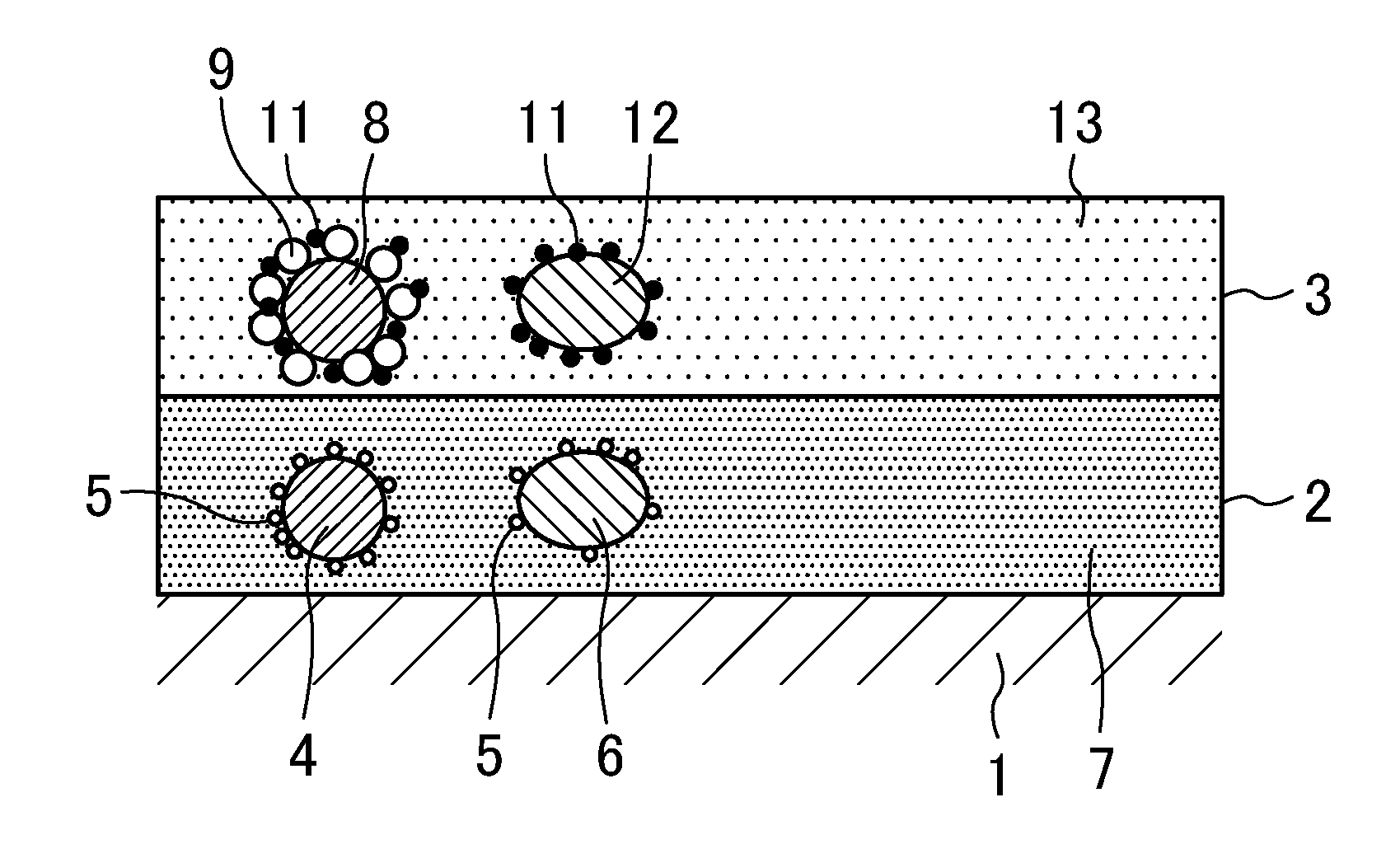
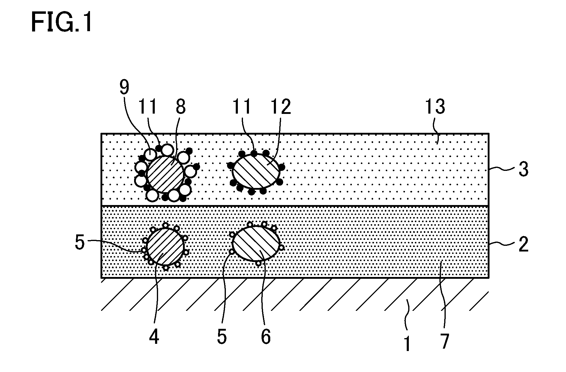
Exhaust gas purification catalyst
a technology of exhaust gas and purification catalyst, which is applied in the direction of physical/chemical process catalysts, other chemical processes, separation processes, etc., can solve the problem of extremely small amount of exhaust gas diffused inside the particles, and achieve the effect of accelerating the purification of exhaust gas, reducing the amount of binder material, and reducing the entire volume of the catalyst layer
- Summary
- Abstract
- Description
- Claims
- Application Information
AI Technical Summary
Benefits of technology
Problems solved by technology
Method used
Image

Examples
example 2
A catalyst of the same structure as the catalyst of Example 1 was prepared in the same manner as Example 1 except that the ZrY binder used in the first catalyst layer 2 was replaced with a ZrNd binder, and the Rh-doped CeO2 binder used in the second catalyst layer 3 was replaced with a Rh-doped CeZr binder.
The ZrNd binder was ZrNd sol obtained by wet grinding ZrO2 containing 3 mol % of Nd2O3. The ZrNd sol had the same particle size distribution as the ZrY sol. The Rh-doped CeZr binder was Rh-doped CeZr sol (Rh concentration: 0.05% by mass) obtained by doping CeZr mixed oxide (CeO2:ZrO2=25:75 (mass ratio)) with Rh. The Rh-doped CeZr sol was prepared in the same manner as the Rh-doped CeO2 sol of Example 1 except that a nitrate solution prepared by dissolving cerium nitrate hexahydrate, a zirconyl nitrate solution, and a rhodium nitrate solution in ion-exchanged water was used. Like the Rh-doped CeO2 sol, the Rh-doped CeZr sol had a particle size distribution (frequency distribution) ...
example 3
A catalyst of the same structure as the catalyst of Example 1 was prepared using the ZrY binder in the same manner as Example 1 except that the Rh-doped CeO2 binder used in the second catalyst layer 3 was replaced with a Rh-doped CeZrNd binder.
The Rh-doped CeZrNd binder was Rh-doped CeZrNd sol (Rh concentration: 0.05% by mass) in which CeZrNd mixed oxide (CeO2:ZrO2:Nd2O3=10:80:10 (mass ratio)) was doped with Rh. The Rh-doped CeZrNd sol was prepared in the same manner as the Rh-doped CeO2 sol of Example 1 except that a nitrate solution prepared by dissolving cerium nitrate hexahydrate, a zirconyl nitrate solution, neodymium nitrate hexahydrate, and a rhodium nitrate solution in ion-exchanged water was used. Like the Rh-doped CeO2 sol, the Rh-doped CeZrNd sol had a particle size distribution (frequency distribution) in which a peak particle size value was in the range of 100 nm to 300 nm, both inclusive.
example 4
A catalyst of the same structure as the catalyst of Example 1 was prepared using the ZrY binder in the same manner as Example 1 except that the Rh-doped CeO2 binder used in the second catalyst layer 3 was replaced with a Rh-doped CeZrLa binder.
The Rh-doped CeZrLa binder was Rh-doped CeZrLa sol (Rh concentration: 0.05% by mass) in which CeZrLa mixed oxide (CeO2:ZrO2:La2O3=10:80:10 (mass ratio)) was doped with Rh. The Rh-doped CeZrLa sol was prepared in the same manner as the Rh-doped CeO2 sol of Example 1 except that a nitrate solution prepared by dissolving cerium nitrate hexahydrate, a zirconyl nitrate solution, lanthanum nitrate hexahydrate, and a rhodium nitrate solution in ion-exchanged water was used. Like the Rh-doped CeO2 sol, the Rh-doped CeZrLa sol had a particle size distribution (frequency distribution) in which a peak particle size value was in the range of a particle diameter of 100 nm to 300 nm, both inclusive.
PUM
| Property | Measurement | Unit |
|---|---|---|
| particle size | aaaaa | aaaaa |
| temperature | aaaaa | aaaaa |
| number average particle diameter | aaaaa | aaaaa |
Abstract
Description
Claims
Application Information