
Control apparatus for internal combustion engine

a control apparatus and internal combustion engine technology, applied in the direction of electric control, combustion-air/fuel-air treatment, instruments, etc., can solve the problems of large purge-air-concentration calculation errors, exhaust gas worsening, and prior-art vaporized-fuel processing devices for engines, etc., to enhance exhaust gas purification

Active Publication Date: 2008-09-23
MITSUBISHI ELECTRIC CORP
View PDF6 Cites 0 Cited by
  • Summary
  • Abstract
  • Description
  • Claims
  • Application Information

AI Technical Summary

Benefits of technology

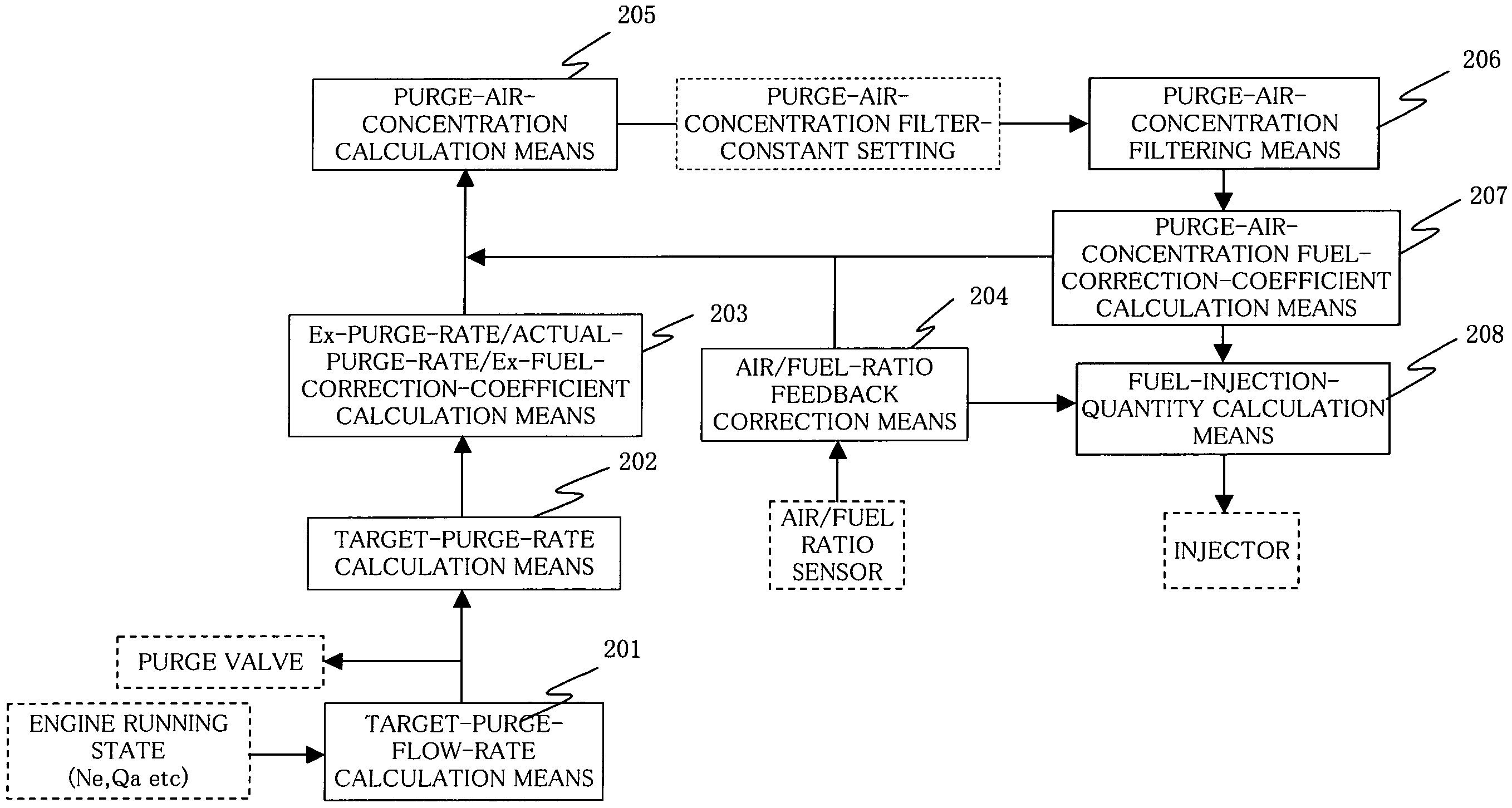
[0011]A control apparatus for an internal combustion engine according to this invention consists, in a control apparatus for an internal combustion engine wherein a fuel injection quantity calculated by fuel-injection-quantity calculation means is corrected with a purge-air-concentration learnt value which has been calculated by subjecting a purge air concentration to purge-air-concentration filtering and wherein fuel in the corrected fuel injection quantity is injected from an injector, in that a filtering effect in the purge-air-concentration filtering is changed in the direction of enhancing exhaust gas purification, between in a case where the purge air concentration is thick and in a case where it is thin. Thus, in the control apparatus for the internal combustion engine wherein the fuel injection quantity calculated by the fuel-injection-quantity calculation means is corrected with the purge-air-concentration learnt value which has been calculated by subjecting the purge air concentration to the purge-air-concentration filtering and wherein the fuel in the corrected fuel injection quantity is injected from the injector, even when the purge air concentration has changed depending upon the running state of the engine, an appropriate air / fuel ratio is established to enhance the exhaust gas purification.

Problems solved by technology

Such prior-art vaporized-fuel processing devices for the engine, however, have had problems as stated below.
Besides, in the case where the purge air concentration is thin, the calculation of the purge air concentration is more susceptible to disturbances (such as air / fuel ratio fluctuations ascribable to an acceleration and a deceleration) other than the purge, and the errors of the purge-air-concentration calculation become large.
Therefore, the air / fuel ratio cannot be maintained at the target air / fuel ratio (for example, a theoretical air / fuel ratio), resulting in the problem that an exhaust gas worsens.

Method used


Image

  • Control apparatus for internal combustion engine
  • Control apparatus for internal combustion engine
  • Control apparatus for internal combustion engine

Examples


embodiment

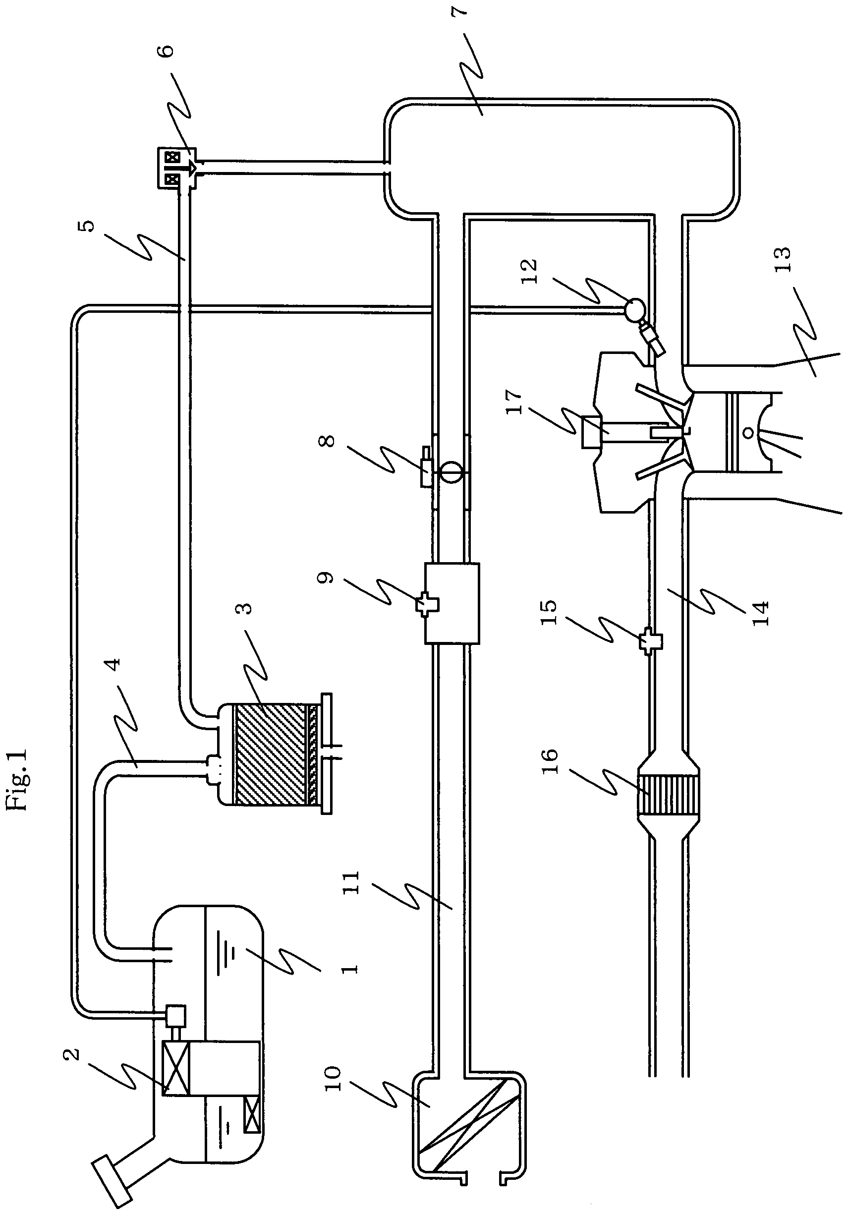
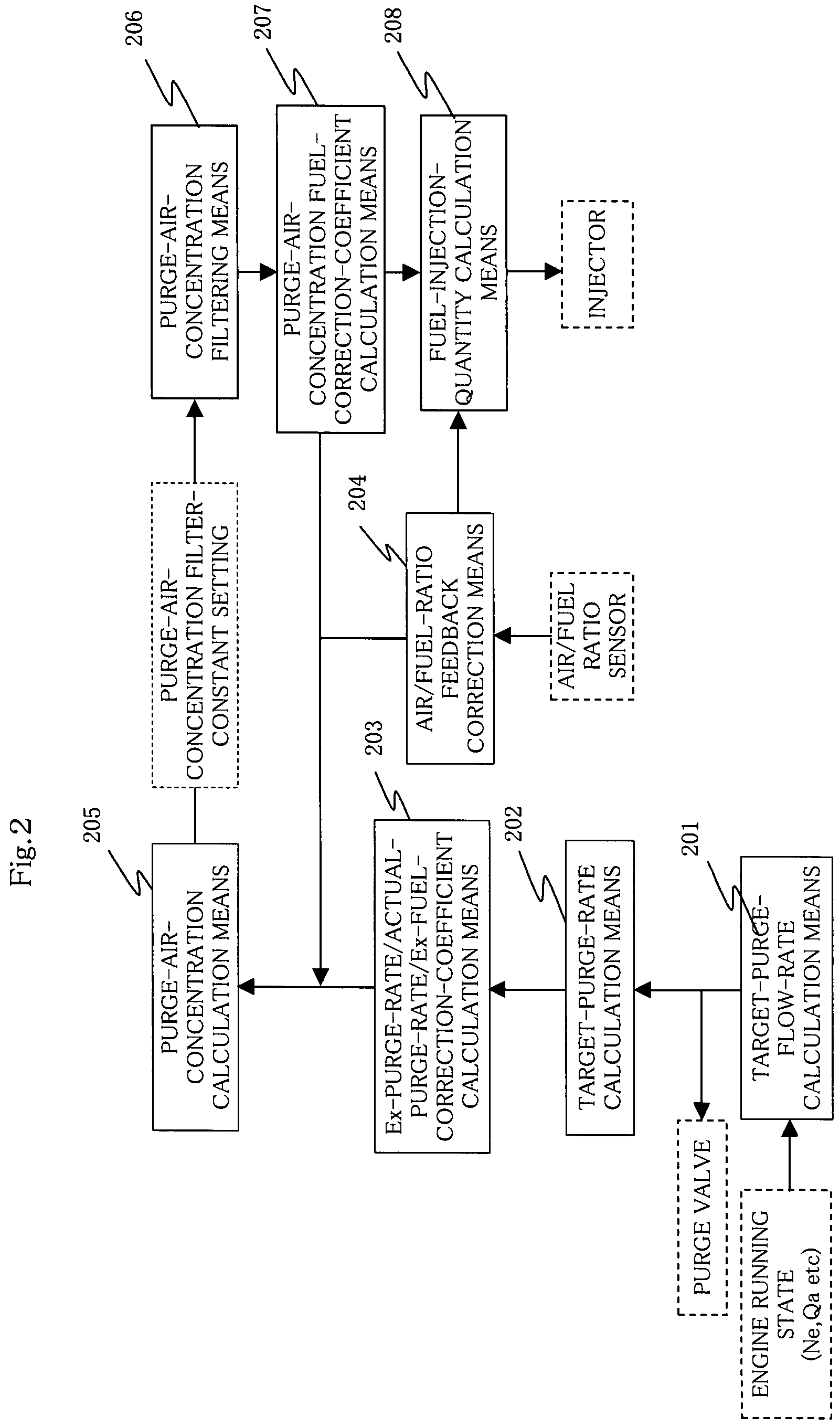
[0022]Now, an embodiment of this invention will be described in conjunction with FIGS. 1-8.

[0023]Schematically shown in FIG. 1 is an example of a control apparatus for an internal combustion engine including a vaporized-fuel processing device. Referring to FIG. 1, an airflow sensor 9 which detects a suction air quantity imbibed through an air cleaner 10, and a throttle valve 8 which controls the suction air quantity are disposed in the suction passage 11 of the internal combustion engine 13. The suction passage 11 is connected to a surge tank 7.

[0024]An injector 12 is disposed in a suction manifold section in the downstream of the surge tank 7, and fuel pumped out by a fuel pump 2 within a fuel tank 1 is injected by the injector 12, whereby the internal combustion engine 13 is fed with the fuel. By the way, in case of an internal combustion engine of in-cylinder injection type not shown, an injector is disposed toward the interior of the combustion chamber of the internal combustion...


PUM


Abstract

A control apparatus for an internal combustion engine, where a calculated fuel injection quantity is corrected with a purge-air-concentration learnt value calculated by subjecting a purge air concentration to purge-air-concentration filtering. A filtering effect in the purge-air-concentration filtering is changed in the direction of enhancing exhaust gas purification, when the purge air concentration is thick and when the purge air concentration is thin, whereby an air / fuel ratio introduced into the internal combustion engine is precisely controlled to a target air / fuel ratio so as to enhance the exhaust gas purification.

Description

BACKGROUND OF THE INVENTION[0001]1. Field of the Invention[0002]This invention relates to a control apparatus for an internal combustion engine, wherein a fuel injection quantity calculated by fuel-injection-quantity calculation means is corrected with purge-air-concentration learnt value which has been calculated by subjecting a purge air concentration to purge-air-concentration filtering, and wherein fuel in the corrected fuel injection quantity is injected from an injector.[0003]2. Description of the Related Art[0004]There has heretofore been known a vaporized-fuel processing device wherein vaporized fuel produced within the fuel feed system of an internal combustion engine, e. g., within a fuel tank is adsorbed and stored in a vaporized-fuel adsorption device (hereinbelow, termed the “canister”) and is thereafter introduced into the suction system of the engine together with air, thereby to purify (hereinbelow, expressed as “purge”) the canister.[0005]Such a vaporized-fuel proce...

Claims


Application Information

Patent Timeline
Patent Type & Authority Patents(United States)
IPC IPC(8): F02D41/00F02M25/08
CPCF02D41/0042F02M25/089F02D41/0045
Inventor ISHIKAWA, OSAMUENOKI, KEIICHI
Owner MITSUBISHI ELECTRIC CORP
Learn More