Method and apparatus for forming container end shells with reinforcing rib

a technology of end shells and reinforcing ribs, which is applied in the field of forming end shells with annular reinforcing ribs, and can solve problems such as undesirable effects

Active Publication Date: 2006-05-02
STOLLE MACHINERY CO LLC +1
View PDF32 Cites 32 Cited by
  • Summary
  • Abstract
  • Description
  • Claims
  • Application Information

AI Technical Summary

Benefits of technology

[0008]Another aspect of the present invention provides for the forming of an annular rolled reinforcing rib in the end shell without complicated and expensive modifications for retrofitting existing double action presses, and which eliminates the need for transfer mechanisms for the transferring of the end shell to an adjacent station or press for final formation of the reinforcing rib in the container end shell.
[0009]A further aspect of the invention provides an apparatus and method for forming the reinforcing rib in the end shell in which the punch core is fluidly mounted on an inner ram of the press, enabling the ram to continue in its cycle after the punch core has reached the bottom of its stroke for clamping the central panel of a disc blank against the die core, which enables the inner ram to time its return stroke to correspond to the start of the return stroke of the outer ram.
[0012]A further feature of the invention is to provide for the simultaneous un-clamping of the punch core and inner and outer pressure sleeves from the formed end shell by timing the cyclical movement of the inner and outer rams, to prevent distortion of the formed metal and in particular, prevent partial unrolling of the formed reinforcing rib.

Problems solved by technology

This is especially undesirable when the container has a removable tab which enables the contents to be drank directly from the container.

Method used


Image

  • Method and apparatus for forming container end shells with reinforcing rib
  • Method and apparatus for forming container end shells with reinforcing rib
  • Method and apparatus for forming container end shells with reinforcing rib

Examples


Embodiment Construction

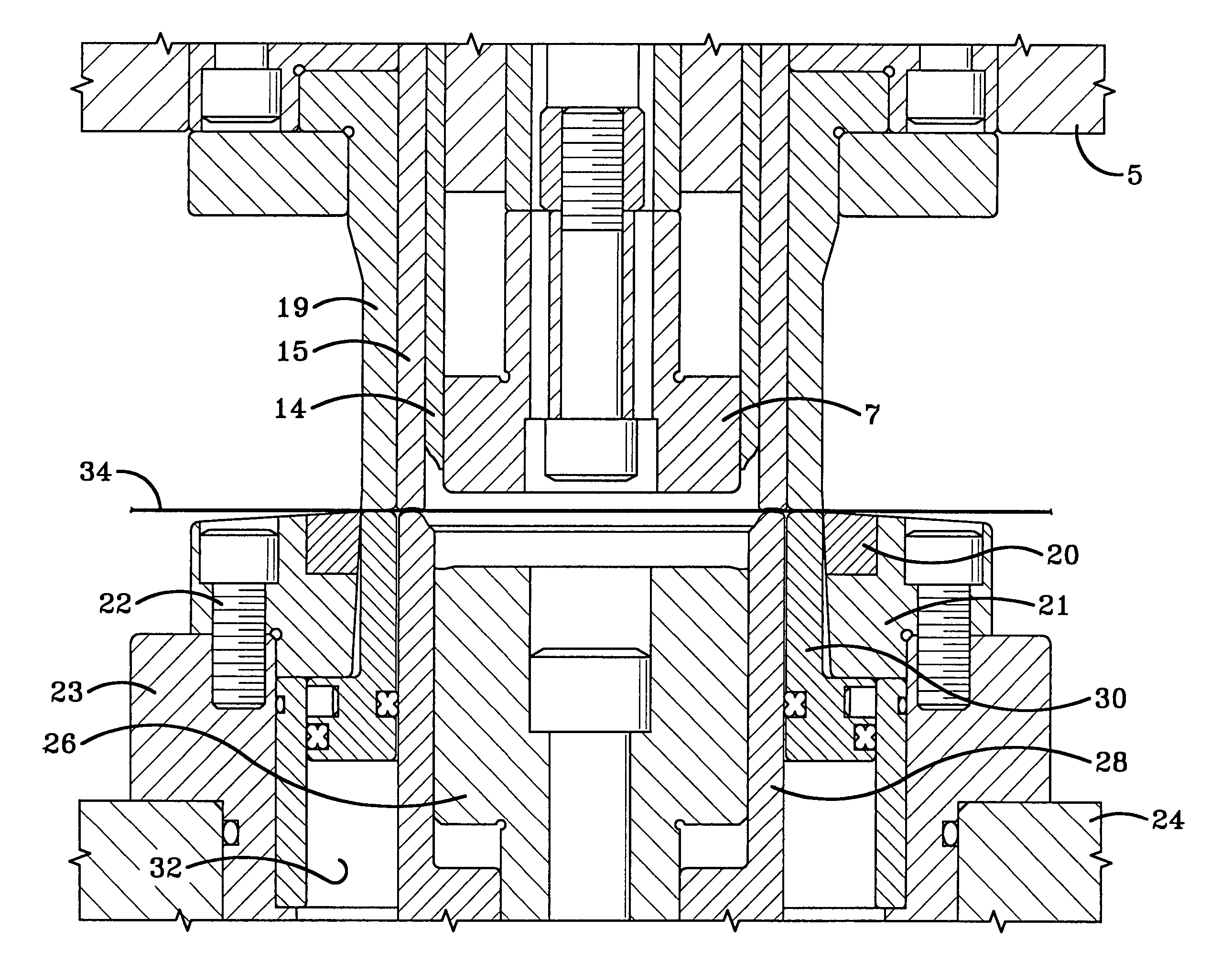
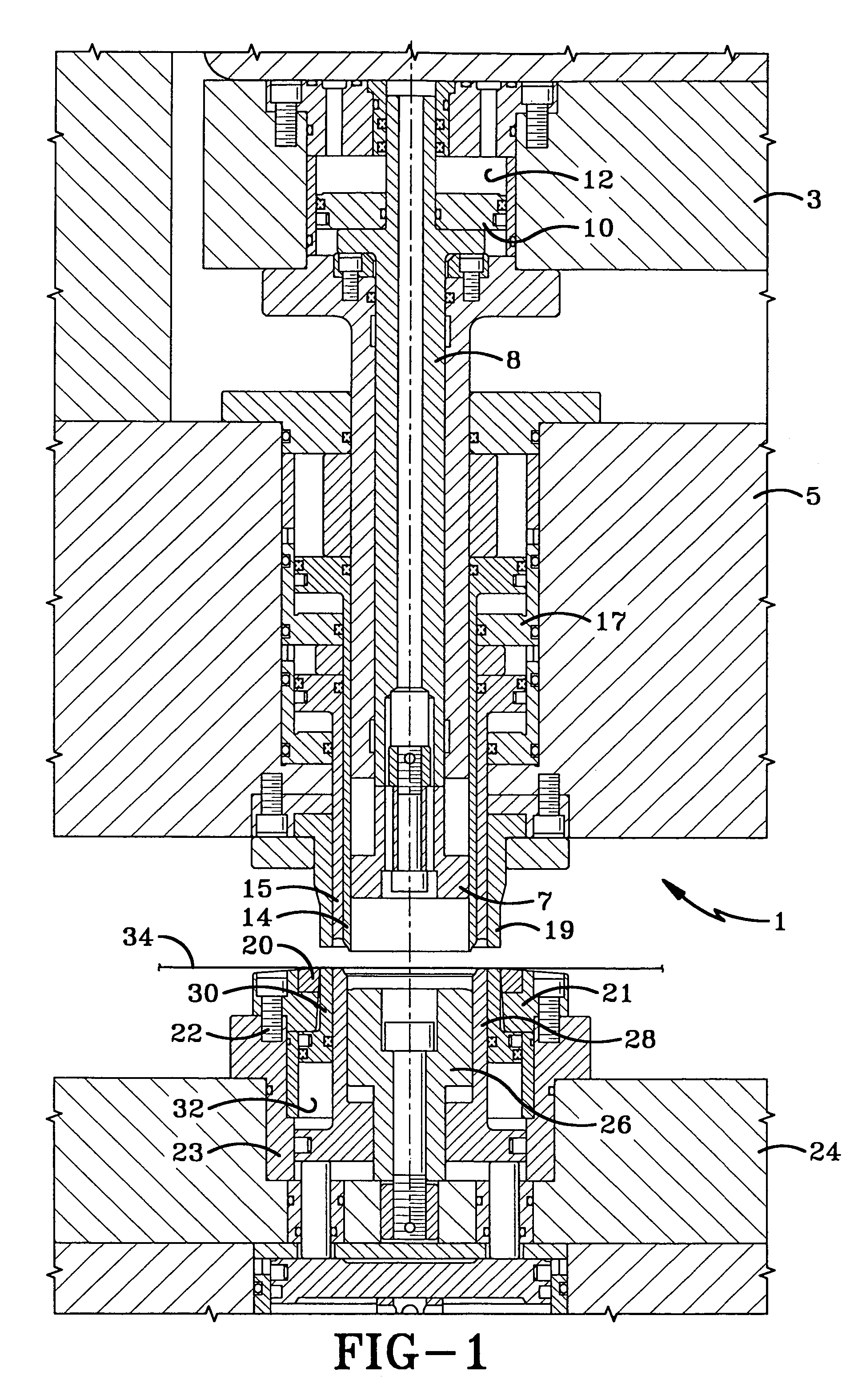
[0032]The method and apparatus of the present invention is utilized in conjunction with a double action press, some examples of which are shown and described in U.S. Pat. Nos. 3,902,348, 5,626,048, and 5,628,224. The main features of the press, which is indicated generally at 1 and shown in FIG. 1, are described briefly below, and include an inner ram 3 and an outer ram 5, only portions of which are shown in FIG. 1.

[0033]A punch core 7, also referred to as draw horn, is connected to the lower end of a punch riser 8, which is reciprocated by inner ram 3. In accordance with one of the features of the invention as shown in FIG. 1, riser 8 and punch core 7 are engaged with a fluid actuated piston 10, which is moved into engagement with punch riser 8 by compressed fluid located within a cylinder 12 formed within inner ram 3. The purpose of this arrangement is discussed further below.

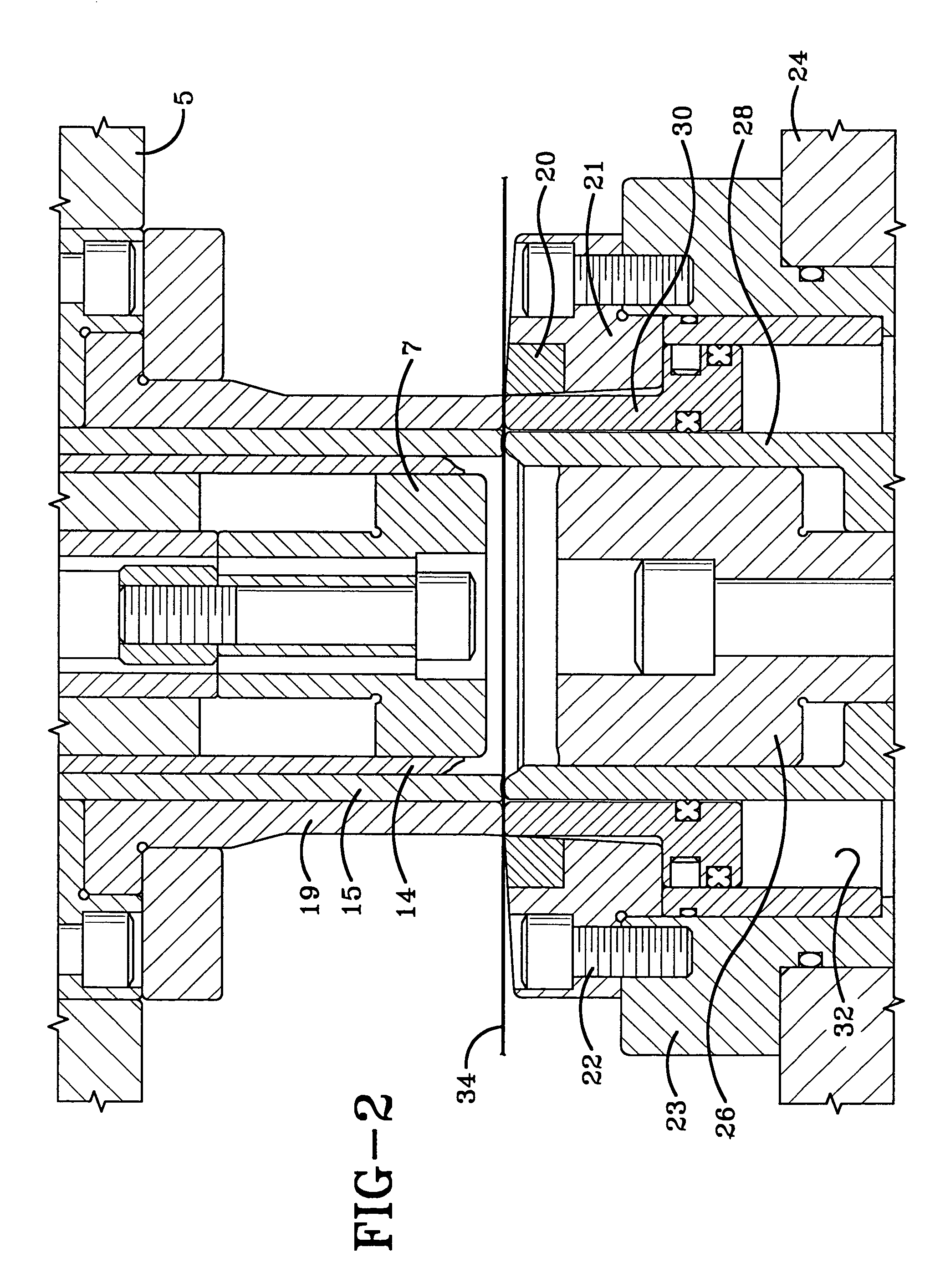
[0034]An inner pressure sleeve 14 and a concentrically located outer pressure sleeve 15 surround punch cor...


PUM

PropertyMeasurementUnit
phase angleaaaaaaaaaa
pressureaaaaaaaaaa
dwell timeaaaaaaaaaa

Abstract

A method and apparatus for forming a rolled reinforcing rib in an end shell of a container body in a single stroke and at a single station of a double action press prior to removal of the shell from the press. A blank disc is cut from sheet material by a punch core advanced by an outer ram. A chuckwall is then formed between a central panel and an outer flange. The central panel is clamped against a die core and a portion of the chuckwall is clamped against a die core ring. An unclamped portion of the chuckwall is located in a void formed between the punch core and die core ring and is rolled into the reinforcing rib upon continued advancement of inner and outer pressure sleeve while maintaining a tight clamping engagement of the central panel and outer flange of the blank disc. Simultaneous removal of the clamping force applied by the punch core and inner and outer pressure sleeves retain the rib in its rolled condition.

Description

BACKGROUND OF THE INVENTION[0001]1. Technical Field[0002]The invention relates to a method and apparatus for forming end shells for metal containers, and particularly to forming end shells having an annular reinforcing rib. Even more particularly, the invention relates to forming the reinforcing rib in the end shell in a single stroke and at a single station of a double action press.[0003]2. Background Information[0004]In the metal container art, containers usually consist of a body formed of lightweight metal, such as aluminum, and a separate end shell for closing the container, also formed of lightweight metal, from strip material. It is desirable in forming the end shell to form a reinforcing rib at the junction of the chuckwall with the central panel of the shell to provide strength and rigidity to the end shell when secured to the container body. Heretofore, these reinforcing ribs were formed as annular grooves in the end panel, examples of which are shown in U.S. Pat. Nos. 4,7...

Claims


Application Information

Patent Timeline
Patent Type & Authority Patents(United States)
IPC IPC(8): B21D51/44B21D51/38
CPCB21D51/38
Inventor MCCLUNG, JAMES A.
Owner STOLLE MACHINERY CO LLC
Why Eureka
Try Eureka