Active measurement and control system for a material cutting apparatus

a technology of material cutting and active measurement, applied in the direction of electric programme control, metal sawing accessories, instruments, etc., can solve the problems of insufficient accuracy of stock material tolerances on metal workpieces, inability to be relied upon as a basis for cutting, and complicated maintenan

Inactive Publication Date: 2006-05-02
HEM
View PDF32 Cites 38 Cited by
  • Summary
  • Abstract
  • Description
  • Claims
  • Application Information

AI Technical Summary

Benefits of technology

[0009]The present invention includes a material cutting apparatus with an active measurement and control system for measuring distal and proximate displacement dimensions on an elongated workpiece and which adjusts the cutting feed length and cutting angle of the saw to compensate in real t

Problems solved by technology

However, when the piece is cut at an angle which is not perpendicular to the axis of the workpiece, referred to as an “angled” cut or “miter” cut, maintaining accuracy becomes much more complicated, particularly when the angle of one end cut differs from the angle of the other end cut.
In the process of maintaining desired tolerances on feed length and cutting angle, variations in the material dimensions and location add complications.
Stock material tolerances on metal workpieces may not be nearly accurate enough to be relied upon as a basis for making the cuts.
Current miter saws have no automatic way of compensating for these problems and controlling the saw accordingly.
The

Method used


Image

  • Active measurement and control system for a material cutting apparatus
  • Active measurement and control system for a material cutting apparatus
  • Active measurement and control system for a material cutting apparatus

Examples


Embodiment Construction

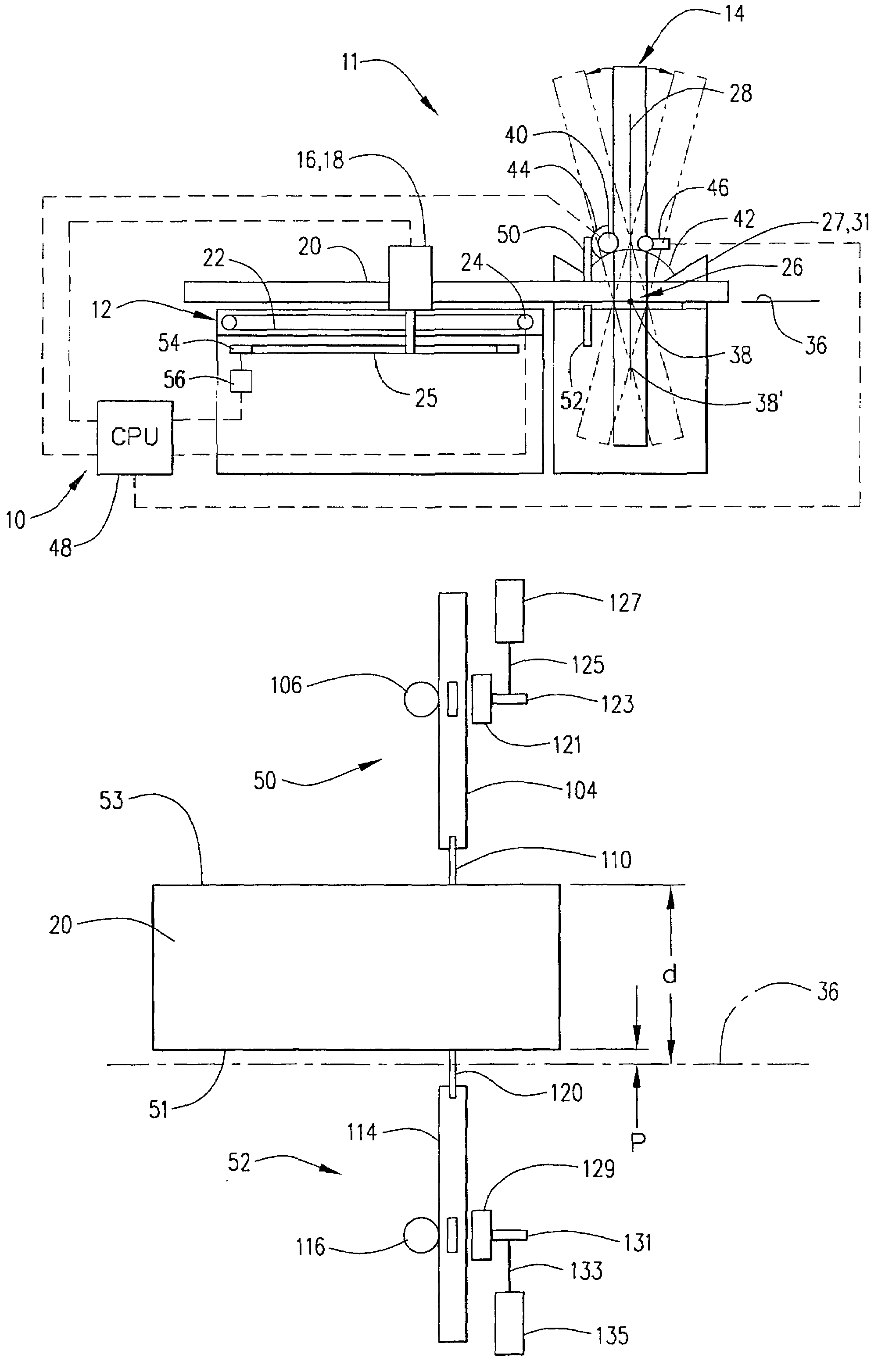
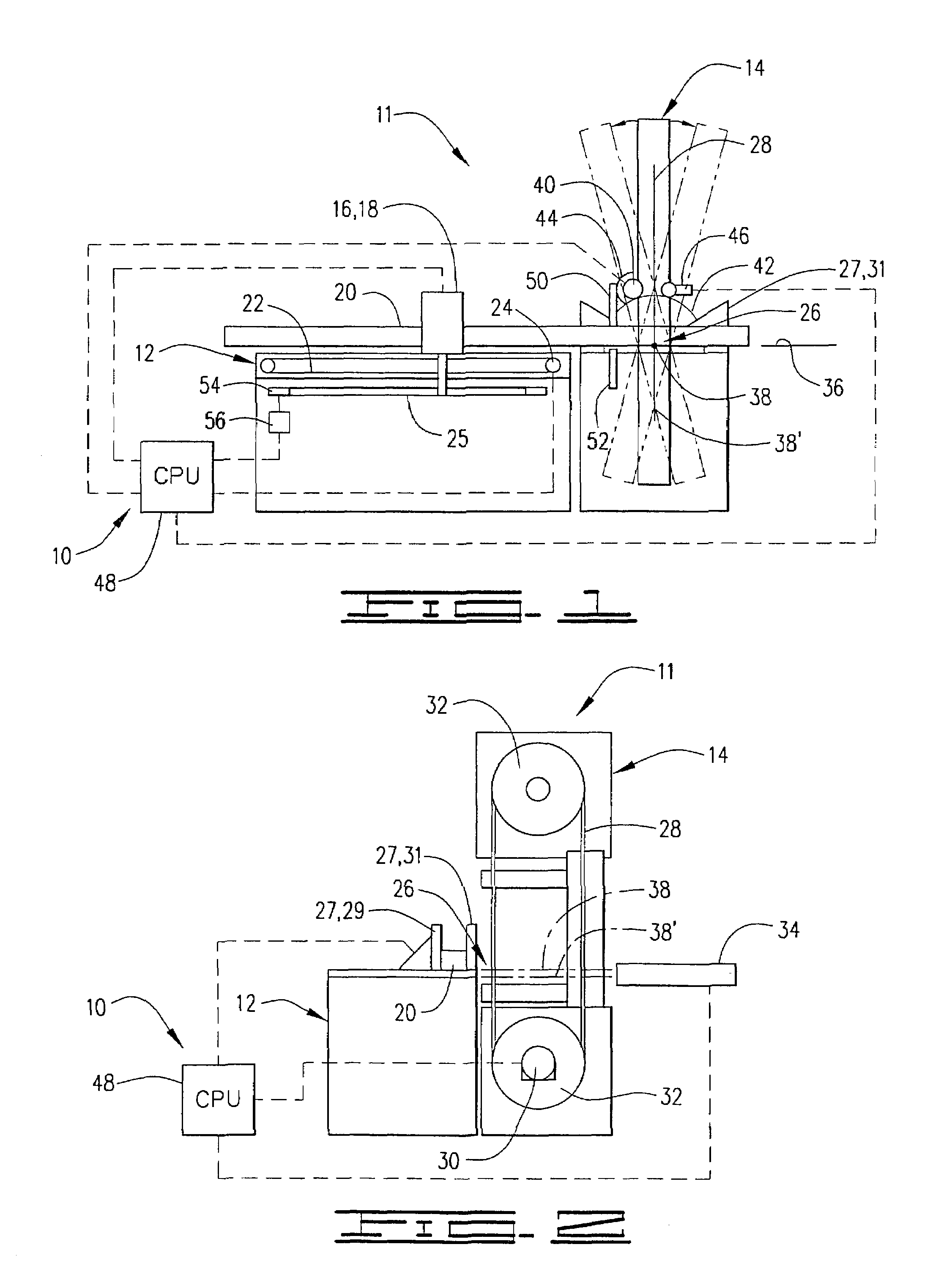
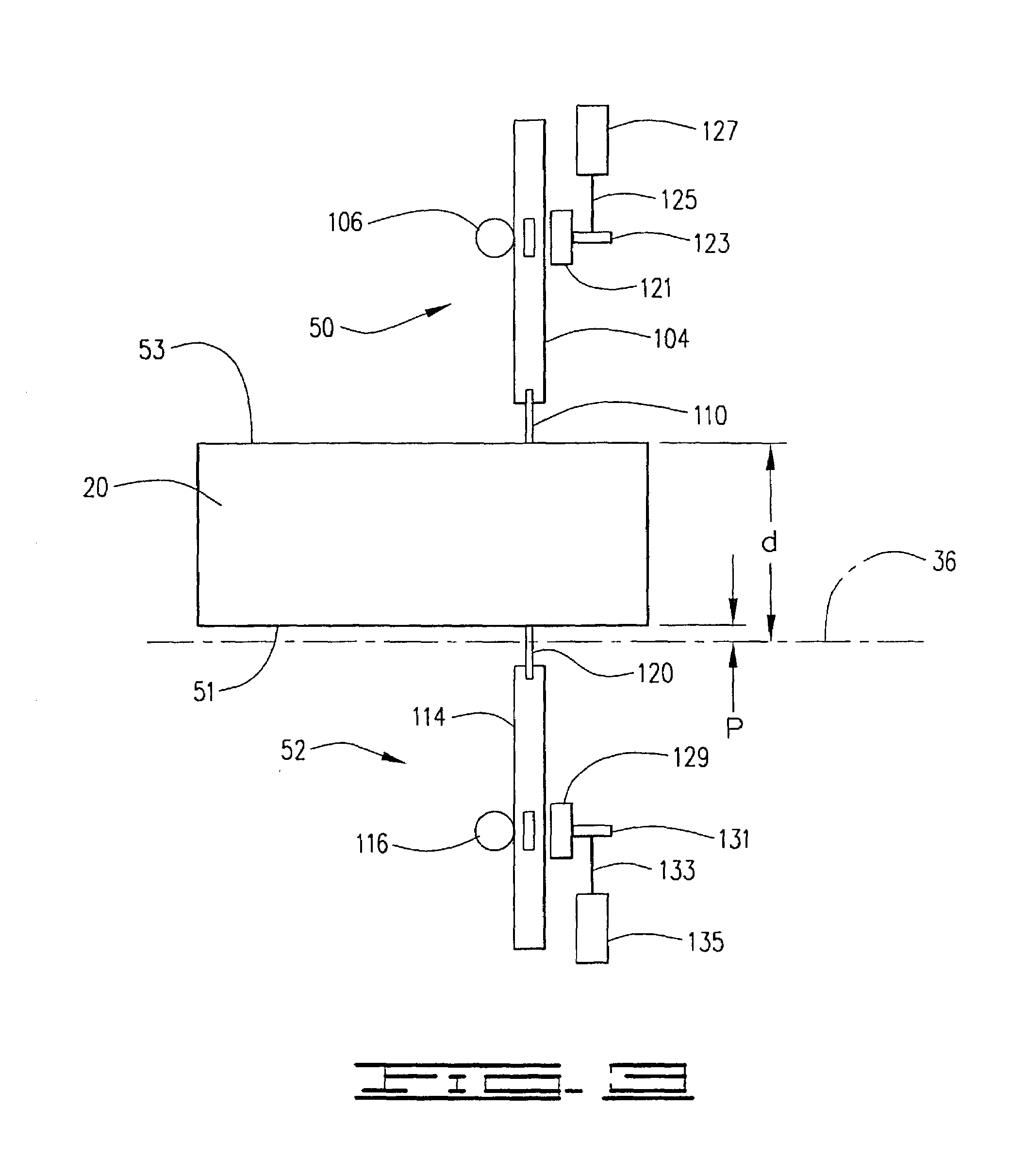
[0047]Referring now to the drawings, and more particularly to FIGS. 1 and 2, the measurement and control system for a material cutting apparatus of the present invention is shown and generally designated by the numeral 10. The cutting apparatus is illustrated as a miter saw designated by the numeral 11. The major components of saw 11 are a feed table 12 and a saw head 14. Feed table 12 moves a measured length of workpiece 20 through cutting area 26 by methods known in the art. For example, but not by way of limitation, feed table 12 includes a shuttle or feed vise 16 with jaws 18 which are used engage a workpiece 20. Jaws 18, and thus, workpiece 20 may be moved longitudinally along feed table 12 in a conventional manner, such as by a chain and sprocket drive 22 connected to vise 16 and powered by a vise drive motor 24. In this way, workpiece 20 can be moved toward a cutting area 26 adjacent to saw head 14. A vise position measuring system 25 is connected to shuttle vise 16.

[0048]A s...


PUM

PropertyMeasurementUnit
Lengthaaaaaaaaaa
Angleaaaaaaaaaa
Areaaaaaaaaaaa

Abstract

An active measurement and control system for a material cutting apparatus. The apparatus comprises a cutting tool which may be pivoted for cutting a workpiece in a cutting area at a selectable angle. The cutting area defines a datum plane, and a feed table with a shuttle vise is used to move the workpiece toward the cutting area. A controller controls the feed distance of the shuttle vise and the cutting angle of the tool in response to a signal from a sensor used for sensing a transverse dimension of the workpiece relative to the datum plane. In this way, the feed distance and cutting angle are adjusted to compensate for variations in the transverse dimension. This transverse dimension can include a displacement from the datum plane of a distal and/or proximate surface of the workpiece. A method of cutting a workpiece is also disclosed.

Description

BACKGROUND OF THE INVENTION[0001]1. Field of the Invention[0002]This invention relates to material cutting apparatus, such as industrial miter saws, and more particularly, to a measurement and control system for these apparatus which provides accurate cutting of elongated workpieces by actively determining variations in material distal and proximate displacement from a known datum plane and compensating therefor.[0003]2. Description of the Prior Art[0004]Material cutting devices, such as saws, used to cut parts from elongated workpieces are well known. Typically, an elongated workpiece is positioned on a feed table and moved toward a cutting area on the saw by means of a shuttle vise. The shuttle vise engages the elongated workpiece and moves it the desired amount (the “feed length”), and the saw is then used to cut the part. Certain accuracy in the cutting of the parts is necessary, and relatively tight tolerances may be desirable.[0005]When making a “square” cut, one in which the ...

Claims


Application Information

Patent Timeline
IPC IPC(8): B23D55/04B23D55/08B26D5/00G05B19/19
CPCB23D55/04B23D55/088B23D59/002G05B19/401G05B2219/50074G05B2219/37404G05B2219/45144G05B2219/50062Y10T83/05Y10T83/051Y10T83/0538Y10T83/0596Y10T83/531Y10T83/536Y10T83/538Y10T83/7101Y10T83/7208Y10T83/7214Y10T83/8773
Inventor HARRIS, GERALD R.RICHARDS, MARK P.JACKSON, MICHAEL L.
Owner HEM
Why Eureka
Try Eureka