Brake arresting device with adaptable brake force for an elevator

a technology of a brake force and an elevator, which is applied in the direction of elevators, braking systems, transportation and packaging, etc., can solve the problems of different retardation values generated at the load receiving means, etc., and achieve the effect of avoiding harm to persons and property

Inactive Publication Date: 2006-05-02
INVENTIO AG
View PDF10 Cites 15 Cited by
  • Summary
  • Abstract
  • Description
  • Claims
  • Application Information

AI Technical Summary

Benefits of technology

[0007]This object is met by a setting device according to the present invention which, through displacement of at least one abutment or the housing, determines the spring deflection of spring elements occurring in the case of a safety braking and thus the spring forces resulting therefrom, wherein these spring elements press the brake wedges against the guide rails of the load receiving means by the stated spring forces. The at least one abutment or the housing can thus be adjusted by means of the setting device in dependence on the magnitude of the mass, which is to be braked, of the load receiving means and the braking force between the brake wedges and the guide rail can thereby be influenced.
[0008]The advantages achieved by the device according to the present invention are that independently of the size of the actual load present in the load receiving means a defined retardation of such a magnitude that harm to persons and property is avoided can be achieved during braking.
[0009]A further advantage of the device according to the present invention is that the adjustment of the abutment or of the housing can be undertaken continuously during travel. This is important in the case of vertical conveying equipment having counter-weights and equipped with compensating cables hanging between the underside of the load receiving means and that of the counter-weight. As the proportion of the mass, which additionally influences a safety braking, of the mentioned compensating cables changes during travel it is advantageous that the position of the abutment or of the housing, on which the braking force arising in the case of a safety braking depends, can be constantly adapted to this change.

Problems solved by technology

The safety brake device described in the foregoing has the disadvantage that in the case of different masses to be braked, different retardation values are generated at the load receiving means.
In the case of large loads in the load receiving means a too small retardation of the load receiving means can thus arise and in the case of small loads an unacceptably high retardation of the load receiving means can arise and thus lead to harm to persons and property.

Method used


Image

  • Brake arresting device with adaptable brake force for an elevator
  • Brake arresting device with adaptable brake force for an elevator
  • Brake arresting device with adaptable brake force for an elevator

Examples


Embodiment Construction

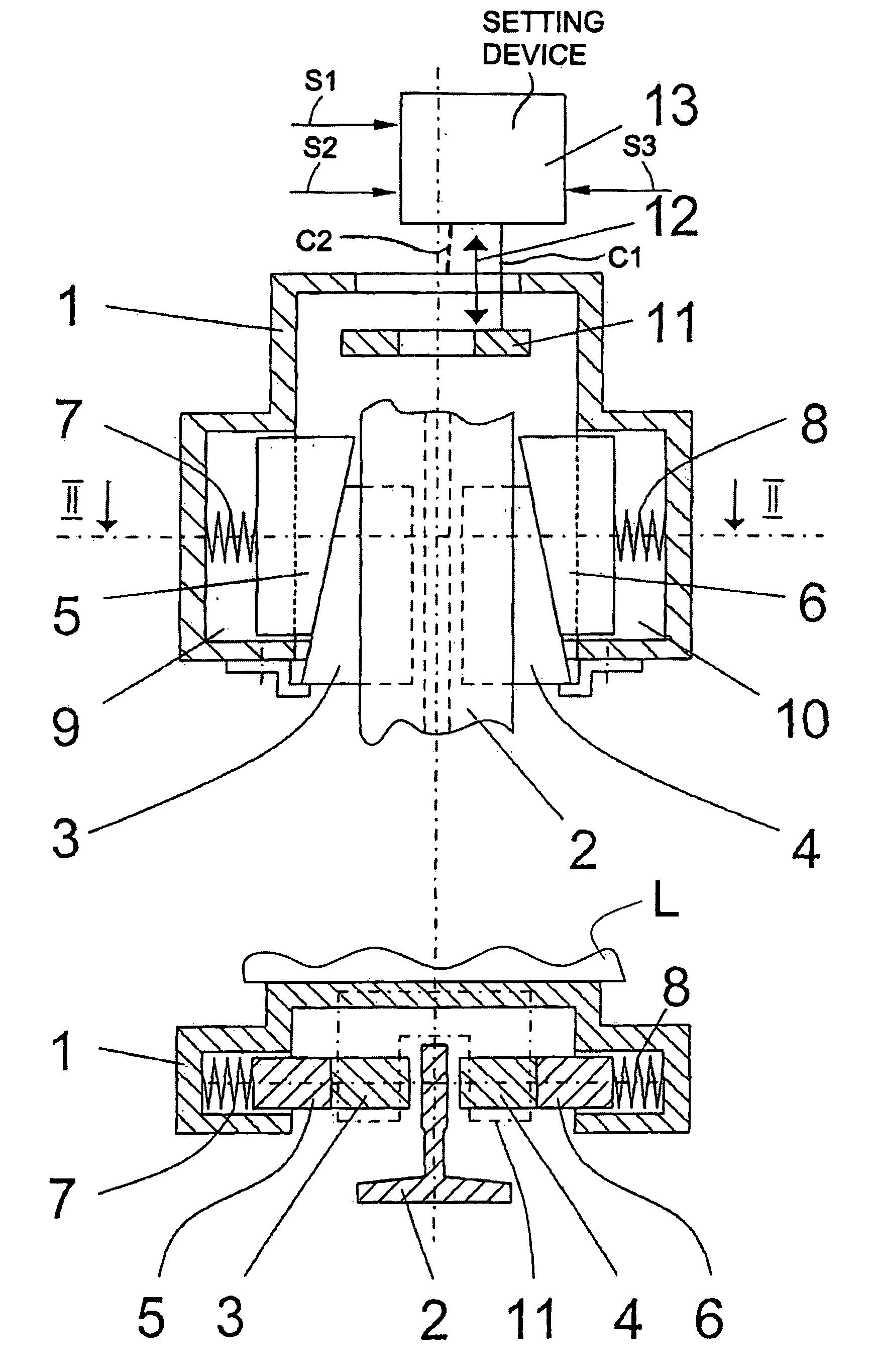
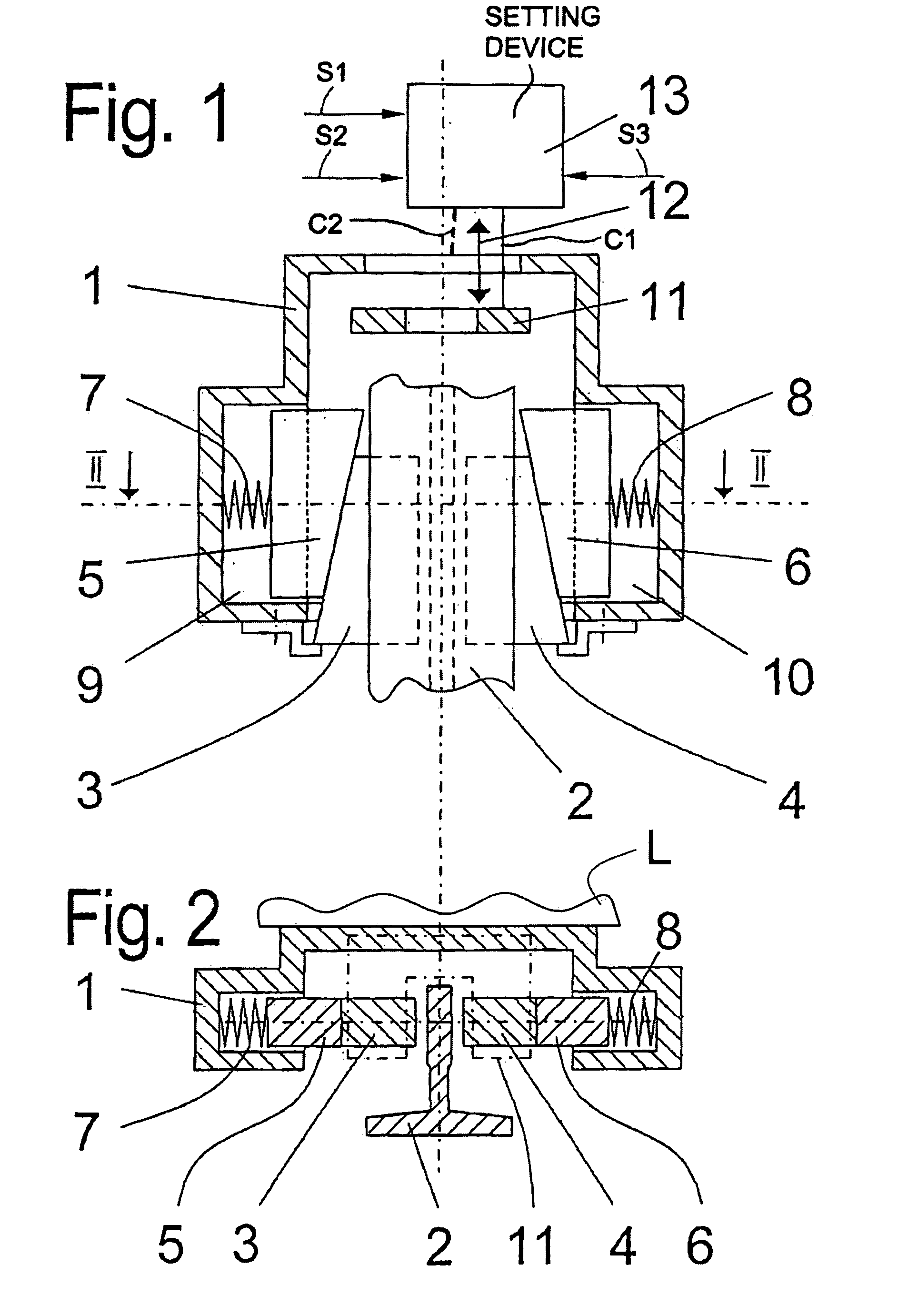
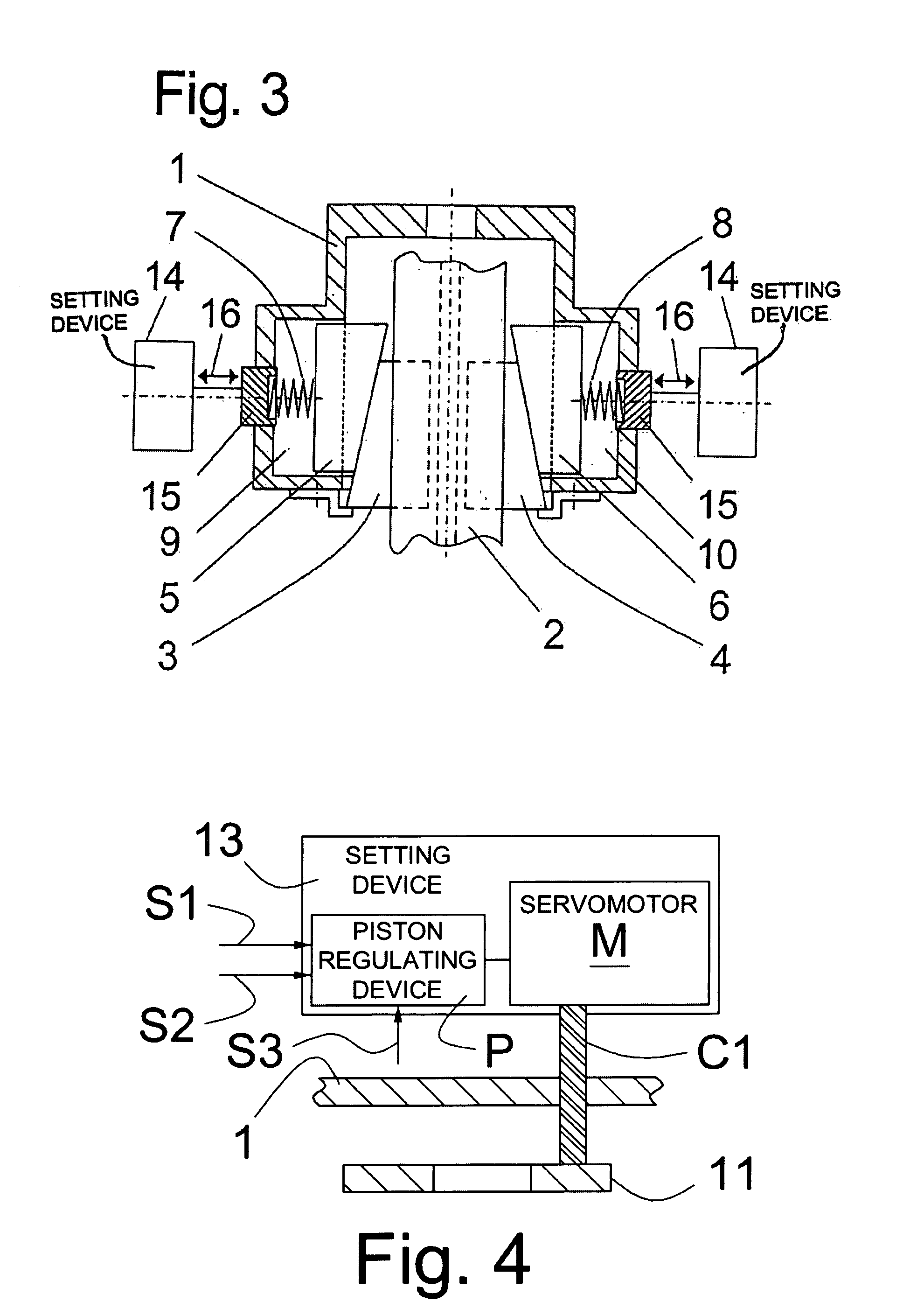
[0015]In FIGS. 1 and 2, there is shown a housing 1 fastened to a load receiving means L of vertical conveying equipment such as an elevator, and a guide rail 2 of the elevator. Brake wedges 3, 4 are arranged at both sides of the guide rail 2 in the housing 1. The brake wedges 3, 4 are supported in the housing 1 by associated counter-shoes 5, 6 and spring elements 7, 8 respectively, wherein the counter-shoes and the spring elements are guided in recesses 9, 10 respectively of the housing 1. Provided above the brake wedges 3, 4 is an abutment 11, which abutment is guided in the housing 1 and can be moved up and down in the direction of a double-headed arrow 12. For this purpose a setting device 13, which stands in operative connection with the abutment 11 and by means of which the abutment can be positioned independently of the actual masses to be braked, is provided. These masses are composed principally of the load present in the load receiving means L, the weight of the elevator ca...


PUM


Abstract

A safety brake device has a setting device moving an abutment or a housing to limit movement of brake wedges engaging a guide rail which limits a braking force applied by the brake wedges. The setting device can continuously adjust the braking force limit in dependence on a magnitude of a mass to be braked.

Description

[0001]This is a continuation of application Ser. No. PCT / CH01 / 00386, filed Jun. 20, 2001.BACKGROUND OF THE INVENTION[0002]The present invention relates generally to a safety brake device for the load receiving means of vertical conveying equipment, including at least one brake wedge, which is arranged in a housing and which on triggering of a braking action acts on a guide rail of the conveying vehicle, and an abutment, which limits the stroke of the at least one brake wedge and thus limits the maximum braking force during the braking process. Moreover, the invention relates to a method of adapting the braking force of this safety brake device to the masses which are to be braked and which act on the load receiving means.[0003]Safety brake devices as described above are used for, for example, passenger elevators, goods elevators and cages in mine conveying installations, wherein the braking process is usually triggered by a limiter cable, which acts on the brake wedge, of a speed li...

Claims


Application Information

Patent Timeline
Patent Type & Authority Patents(United States)
IPC IPC(8): B61H7/12B66B5/22
CPCB66B5/22
Inventor SIMMONDS, OLIVERHUGEL, STEFANMAURY, JULIENMORI, PETERAESCHLIMANN, PETER
Owner INVENTIO AG
Why Eureka
Try Eureka