Diagonally divided bottle with curved line of division distinct from edge curve

a bottle and curve technology, applied in the field of plastic containers and nozzles, can solve the problems of unsuitable for food products, unsuitable for upright storage on a shelf, unduly complicated and expensive for manufacturers, and achieve the effect of reducing the intermixing of ingredients

Inactive Publication Date: 2006-05-02
HANTMAN KEN S +2
View PDF16 Cites 33 Cited by
  • Summary
  • Abstract
  • Description
  • Claims
  • Application Information

AI Technical Summary

Benefits of technology

[0022]The invention also includes an ergonomically improved flip-cap oriented so that the lip an détente for the flip-cap top is perpendicular to the divider wall which itself is angled at less than or equal to 90 degrees and preferably approximately 30 degrees to a line d

Problems solved by technology

However, this design would not stand on a shelf nor be suitable to contents of greater viscosity.
This would not be suitable to storage in an upright position on a shelf nor is it suitable for food products due to the strong association of such tubes with toiletry and medicinal items.
Various containers (e.g., Huenergardt, U.S. Pat. No. 2,661,870, December, 1953; Kuster, U.S. Pat. No. 3,197,071, December, 1962; Hoffman, U.S. Pat. No. 3,206,074, September, 1965; Newton, U.S. Pat. No. 3,467,269, September, 1969) present designs suitable to displaying and storing on a shelf, however they are unduly complicated and expensive to manufacturer.
However, an adequate method to control the blow-molding of such a dual chamber is not reliably described.
A further disadvantage is the splotchy appearance of glue on the dividing surface.
The intermixing produces an unsavory appearance and loses any aesthetic delight of drawing designs in a dual color stream

Method used


Image

  • Diagonally divided bottle with curved line of division distinct from edge curve
  • Diagonally divided bottle with curved line of division distinct from edge curve
  • Diagonally divided bottle with curved line of division distinct from edge curve

Examples


Embodiment Construction

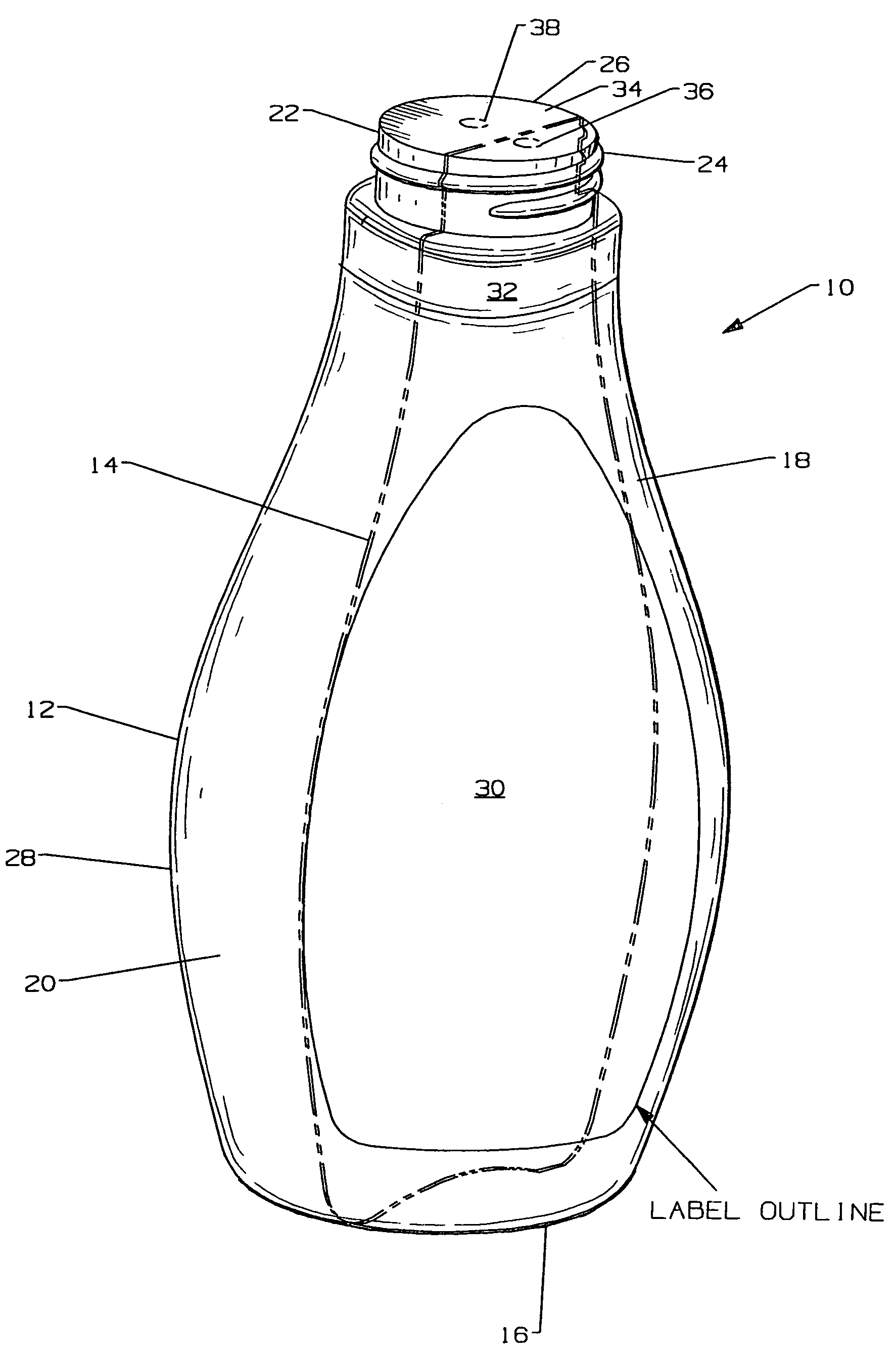
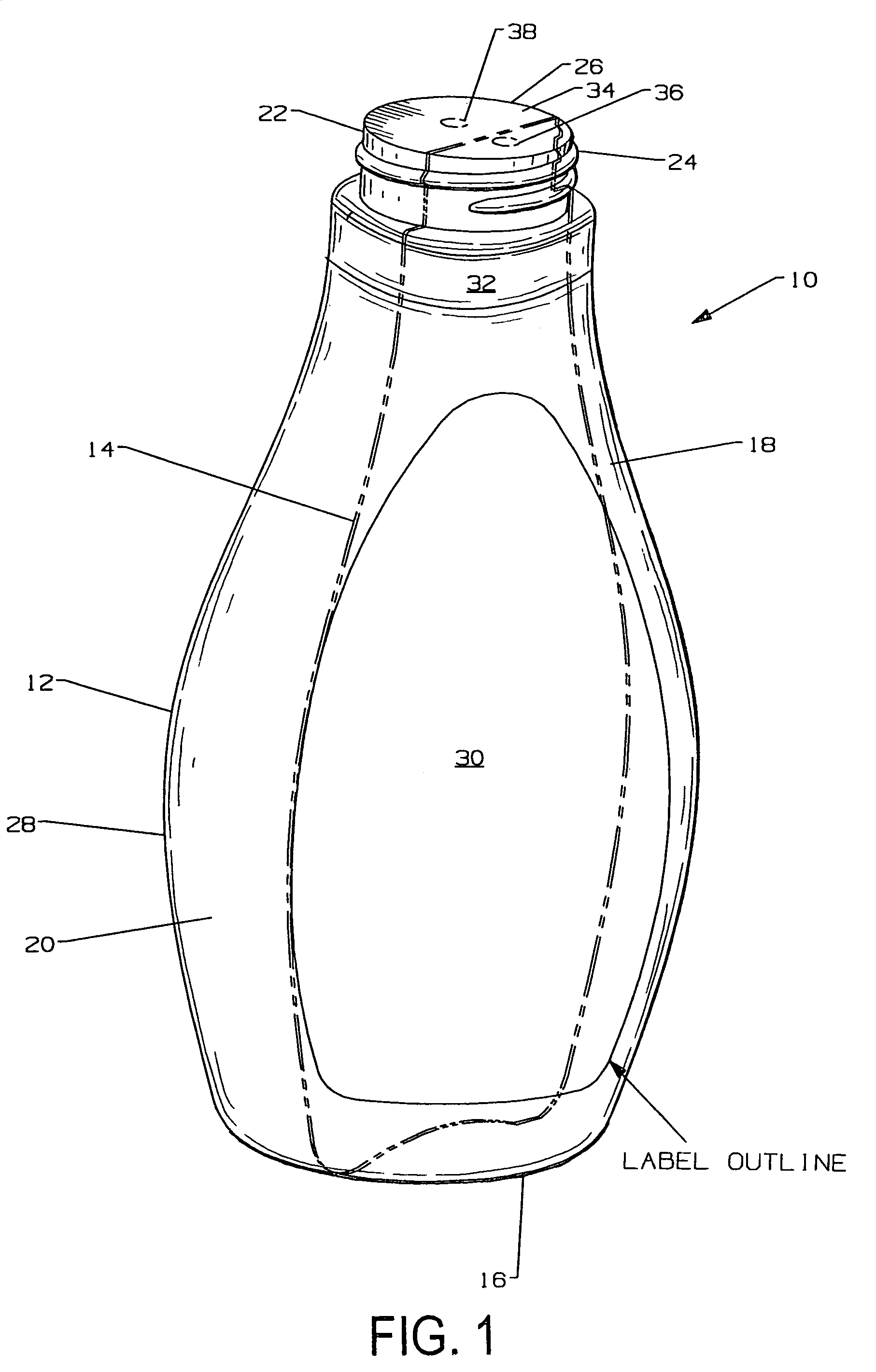
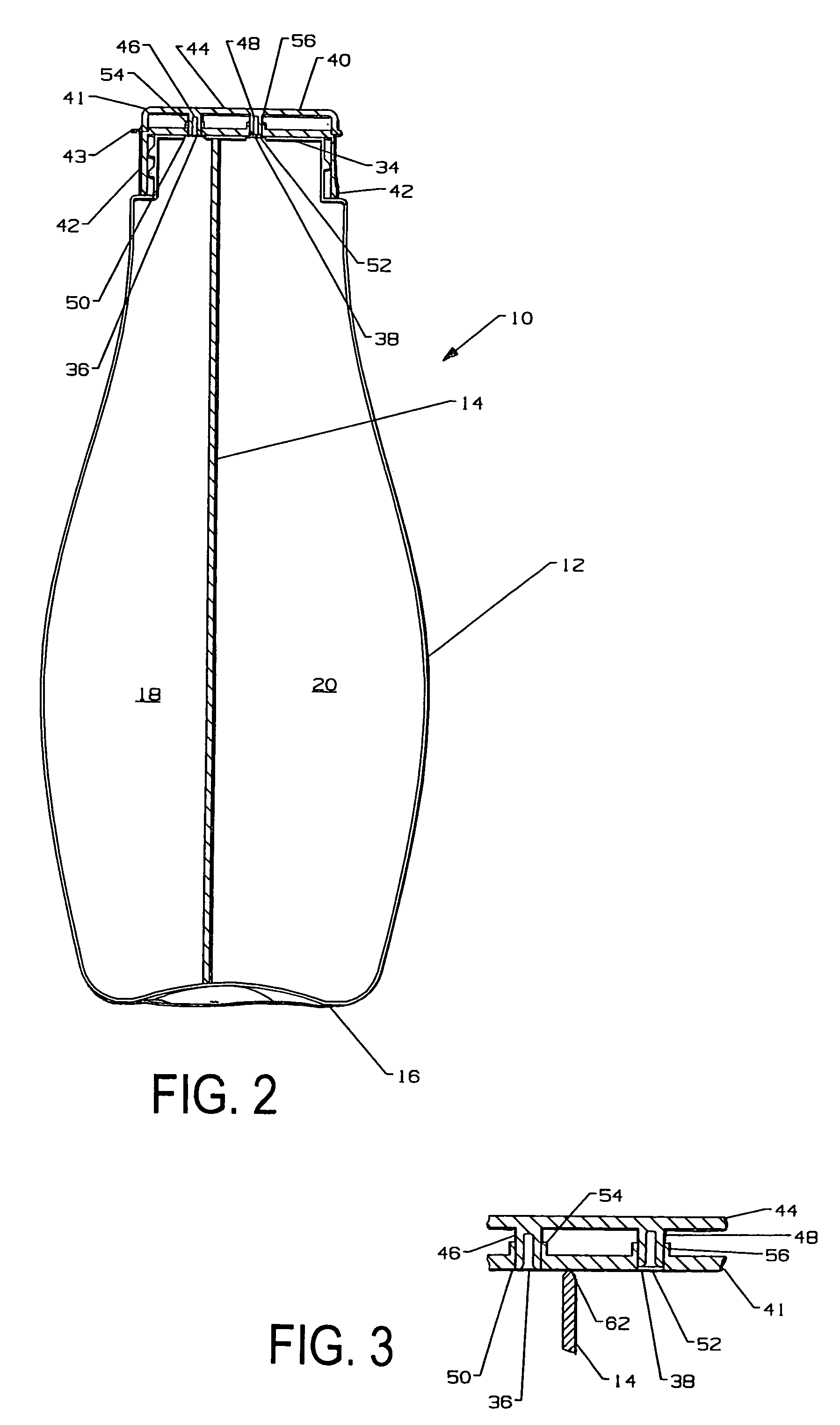
[0034]In accordance with the present invention a dual (or multiple) chamber bottle comprises a curved outer bottle formed as or forming a single container. The bottle is internally diagonally divided by an inner (preferably) planar curtain or wall, forming a curving line at the point of intersection with the outer bottle when viewed from the face or obverse face of the bottle.

[0035]FIG. 1 shows a diagonally divided bottle 10 in accordance with a preferred embodiment of the invention. The bottle 10 includes an annular outer wall 12, an inner wall (or curtain) 14 and a bottom wall 16. The annular outer wall 12 and bottom wall cooperate to form an interior divided by the inner wall 14, which seals to the outer wall 12, preferably during a blow-molding process, to form a fluid tight seal between the divided interior, and to define separate interior chambers 18, 20.

[0036]The outer wall 12 includes an upstanding mouth 22, preferably having an exterior threaded neck 24 for allowing rotatio...


PUM

PropertyMeasurementUnit
Angleaaaaaaaaaa
Angleaaaaaaaaaa
Shapeaaaaaaaaaa

Abstract

A diagonally divided bottle in accordance with the preferred embodiments preferably has a greater width than depth. The bottle includes an outer wall, a diagonal inner wall and a bottom wall. The outer wall and the bottom wall cooperate to form an interior divided by the inner wall. The inner wall intersects the outer wall and to the bottom wall to form a fluid tight seal between the divided interior, with the divided interior defining separate interior chambers. The inner wall is arranged at an angle diagonal to a plane tangential to the front of the bottle such that products contained in each interior chamber are simultaneously viewed when the bottle is observed from the front of the bottle.

Description

[0001]This application is a non-provisional of provisional Nos. 60 / 388,581 and 60 / 388,506 filed Jun. 13, 2002.FIELD OF THE INVENTION[0002]This invention relates to plastic containers and nozzles, specifically to ones that are divided into two or more sections.BACKGROUND OF THE INVENTION[0003]Containers or bottles made of leather, glass, plastic and other materials have been manufactured to store and deliver ingredients such as different liquors, body moisturizing lotions, chemical drain cleaners, two-part epoxies, drugs, food products including condiments, and other things which either benefit by being separately dispersed or are activated at the time of dispersal by mixing.[0004]A dual chambered flask or bottle invented by Jacob Gruenebaum (U.S. Pat. No. 284,127) in August 1883 presented two oppositely inclined necks to obviate the need to raise the flask overly much for the purpose of imbibing its liquors or wines. However, this design would not stand on a shelf nor be suitable to...

Claims


Application Information

Patent Timeline
IPC IPC(8): B65D35/22
CPCB29C49/0078B65D81/3288B65D1/04B29C49/04B29C2049/6027B29C2049/609B29C2049/6063B29C2949/075B29C2949/074
Inventor HANTMAN, KEN S.LINDSEY, RAYHANTMAN, CHRIS S.
Owner HANTMAN KEN S
Why Eureka
Try Eureka