Quick release vise

Inactive Publication Date: 2006-05-02
INDAL TECH
View PDF10 Cites 35 Cited by
  • Summary
  • Abstract
  • Description
  • Claims
  • Application Information

AI Technical Summary

Benefits of technology

[0008]The present invention generally relates to a method and apparatus for clamping a work piece. The apparatus generally includes a stationary jaw with a first clamping surface and a moveable jaw with a second clamping surface connected and operated

Problems solved by technology

However, there are several

Method used


Image

  • Quick release vise
  • Quick release vise
  • Quick release vise

Examples


Embodiment Construction

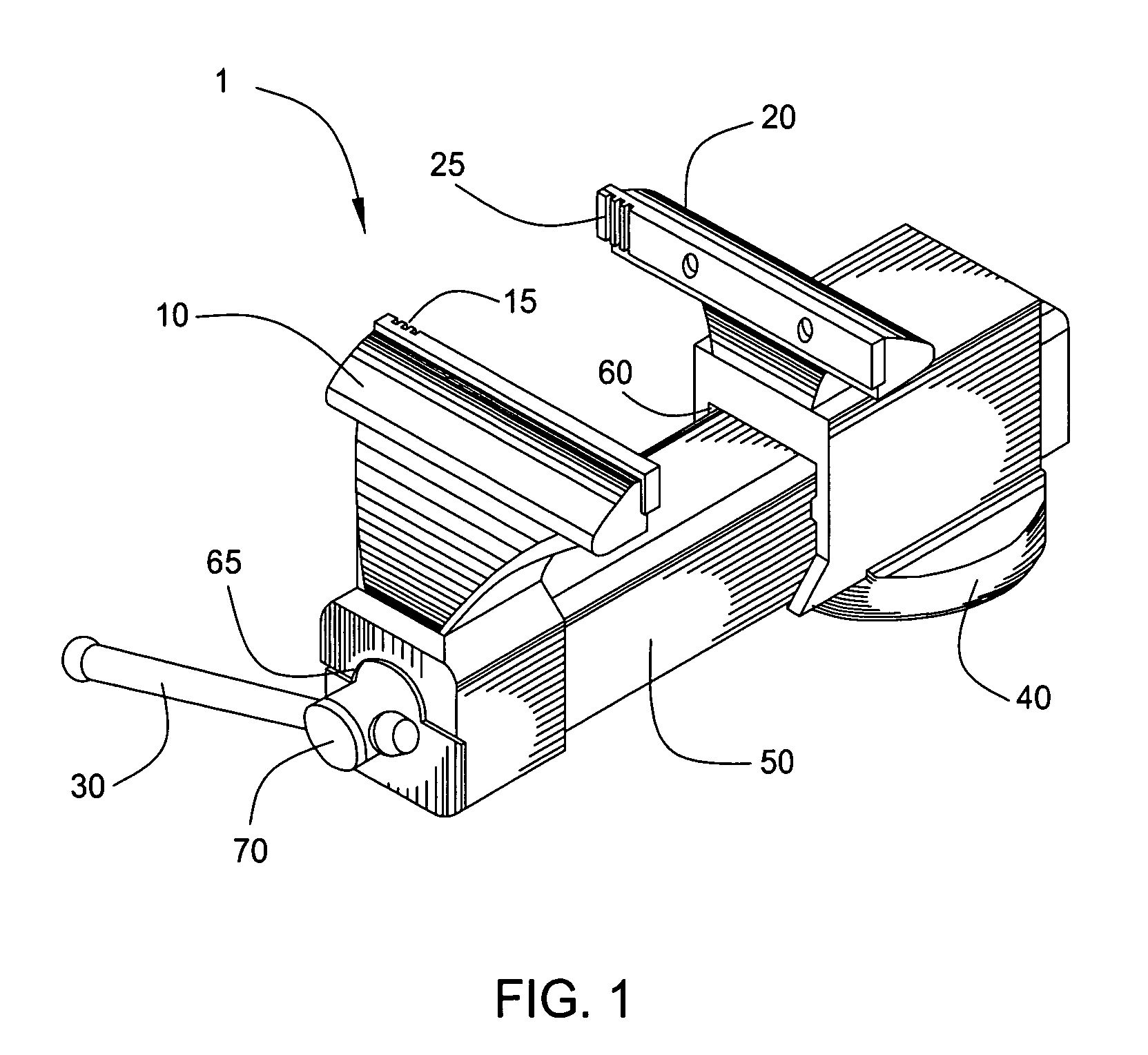
[0020]FIG. 1 illustrates a perspective view of a vise 1 which is configured to incorporate embodiments of the present invention. The vise 1 includes a moveable jaw 10 which includes a clamping surface 15. The moveable jaw 10 is attached to a channel 50 which is guided through an opening 60 of the housing of a fixed jaw 20. The fixed jaw 20 is attached to a base 40 for mounting the vise 1 to a surface. The fixed jaw 20 includes a clamping surface 25. A spindle 70 is attached to both the moveable jaw 10 and the fixed jaw 20 and projects from the moveable jaw 10 at opening 65. The spindle 70 is attached to a lever 30. The lever 30 moves the moveable jaw 10 toward the fixed jaw 20 when rotated in one direction. The lever 30 releases the fixed jaw 20 from the spindle 70 when rotated in the opposite direction, thus allowing free movement of the moveable jaw 10 (described further below).

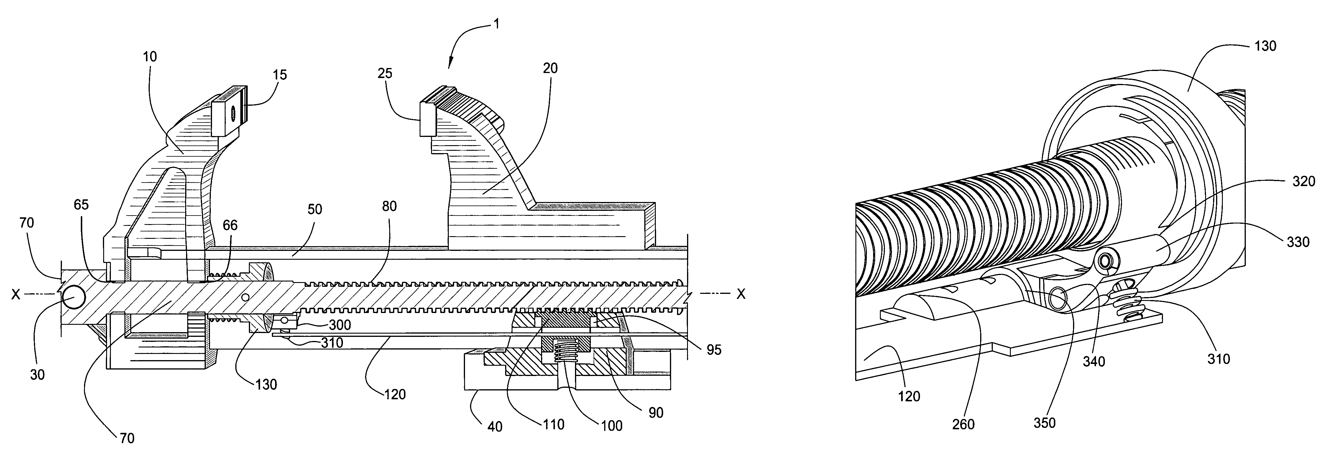
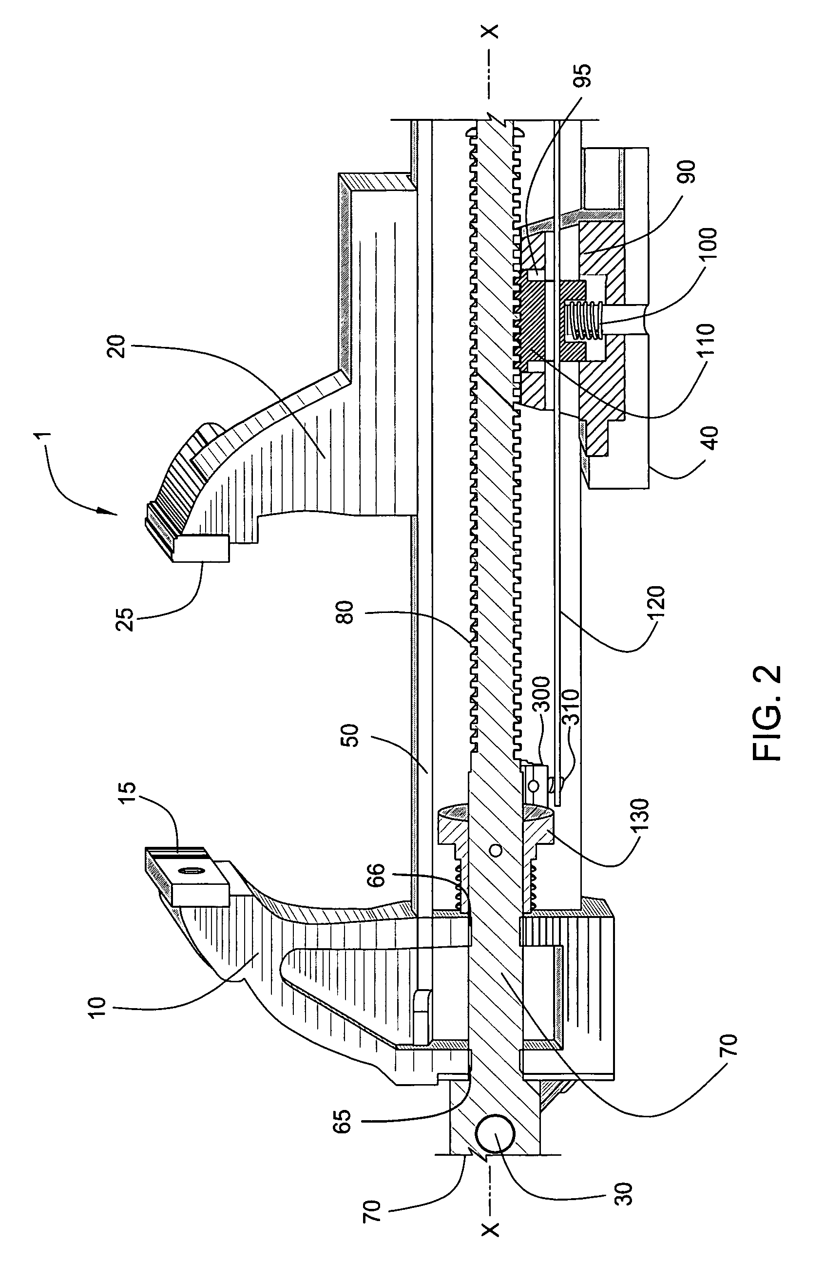
[0021]FIG. 2 shows a schematic cross sectional view of the vise 1. The figure depicts the spindle 70 goi...


PUM


Abstract

A method and apparatus for clamping a work piece is disclosed. The apparatus generally includes a stationary jaw with a first clamping surface and a moveable jaw with a second clamping surface connected and operated by a spindle. The spindle moves the stationary jaw and moveable jaw toward each other when rotated in one direction. The spindle disengages the stationary jaw when rotated in the opposite direction, thus allowing for rapid adjustment of the apparatus.

Description

BACKGROUND OF THE INVENTION[0001]1. Field of the Invention[0002]Embodiments of the present invention generally relate to a hand tool and more particularly to a vise. More particularly still, embodiments of the invention relate to a table top mounted vise with improved performance and utility.[0003]2. Description of the Related Art[0004]Vises are used in order to temporarily hold one or more objects so that work can be performed on them. Traditional table top mounted vises have existed for years. A typical vise is composed of a stationary jaw with a base that can be mounted to a surface. There is a moveable jaw and a guide rod(s) that allows the moveable jaw to move smoothly toward and away from the stationary jaw. Each jaw has a clamping surface for holding a work piece. Further, the vise has a screw and lever system which operates the moveable jaw. The screw typically has a relatively fine pitched thread which provides a large mechanical advantage such that a relatively small amoun...

Claims


Application Information

Patent Timeline
IPC IPC(8): B25B1/02
CPCB25B1/125
Inventor GASPARYAN, KARENHAKHINYAN, PATVAKAN
Owner INDAL TECH
Why Eureka
Try Eureka