Bolted connection of two components with alignment compensation in three dimensions

a technology of alignment compensation and bolts, applied in the direction of rod connections, screws, washers, etc., can solve the problems of high labor and time, complicated connection arrangements, and high volume or space requirements of parts, and achieve the effect of enhancing the radial spreading or wedging effect of threaded standoff, easy wedged or spread outwardly

Active Publication Date: 2006-05-02
DIEHL AIRCABIN
View PDF8 Cites 34 Cited by
  • Summary
  • Abstract
  • Description
  • Claims
  • Application Information

AI Technical Summary

Benefits of technology

[0005]In view of the above, it is an object of the invention to provide a connection arrangement as well as a method of assembling or installing the same, for connecting two components while compensating for any positional, dimensional, or alignment deviations of the two components along three axes, i.e. in three dimensions, within a prescribed adjustment or compensating range. Furthermore, it is an object of the invention to provide such a connection arrangement and method, whereby a positive form-locked play-free rigid and stable joint of the two components is achieved, in a manner that is robust and durable, without being released or loosened by external influences such as vibrations, temperature variations, moisture, or the like. The invention further aims to avoid or overcome the disadvantages of the prior art, and to achieve additional advantages, as apparent from the present specification. The attainment of these objects is, however, not a required limitation of the present invention.
[0011]In this manner, any misalignments between the two components within the permissible range in three dimensions can be accommodated, and the two components are tightly secured in a play-free and positive form-locked manner.
[0015]In order to enhance the radial spreading or wedging effect of the threaded standoff being clamped radially outwardly against the internal threading of the first hole of the first component, the end of the threaded standoff facing away from the second component can be radially tapered to become thinner toward the end, and can be provided with axially extending slots, so that the end portion of the threaded standoff is provided with plural separate tabs forming a castellated configuration. This allows the separate tabs to be more easily wedged or spread outwardly. Also, the bolt arrangement may comprise the clamping cone as a conically configured bolt head permanently fixed on one end of the bolt shaft with a threaded nut on the opposite end, or preferably may comprise the clamping cone provided with an internal threading being threaded onto one end of the bolt shaft in the manner of a cone-shaped nut with a fixed bolt head on the opposite end of the shaft.
[0016]The above objects have further been achieved according to the invention in a method of installing, aligning or adjusting, and then securing the above described mechanical connection arrangement. The method involves screwing the threaded standoff into the threaded first hole of the first component to the proper extent for the proper adjusted spacing distance compensation as mentioned above. Next, the eccentric arrangement is adjusted to align the bolt hole of the eccentric arrangement with the bolt hole of the threaded standoff. Next, the bolt arrangement is inserted through the bolt holes, and the bolt arrangement is tightened so as to apply an axial clamping effect along the axis of the bolt shaft between the two components, and a radial spreading and clamping effect of radially outwardly spreading the threaded standoff against the internal threading of the first hole of the first component.

Problems solved by technology

As a result, the connection has a relatively high volume or space requirement for its parts and particularly for the installation thereof.
Moreover, for the same reasons, the known connection arrangements are complicated, expensive, and require a high effort and time for the installation thereof.
Another disadvantage is the relatively high total weight of such connection arrangements due to the additional individual parts that are needed.

Method used


Image

  • Bolted connection of two components with alignment compensation in three dimensions
  • Bolted connection of two components with alignment compensation in three dimensions
  • Bolted connection of two components with alignment compensation in three dimensions

Examples


Embodiment Construction

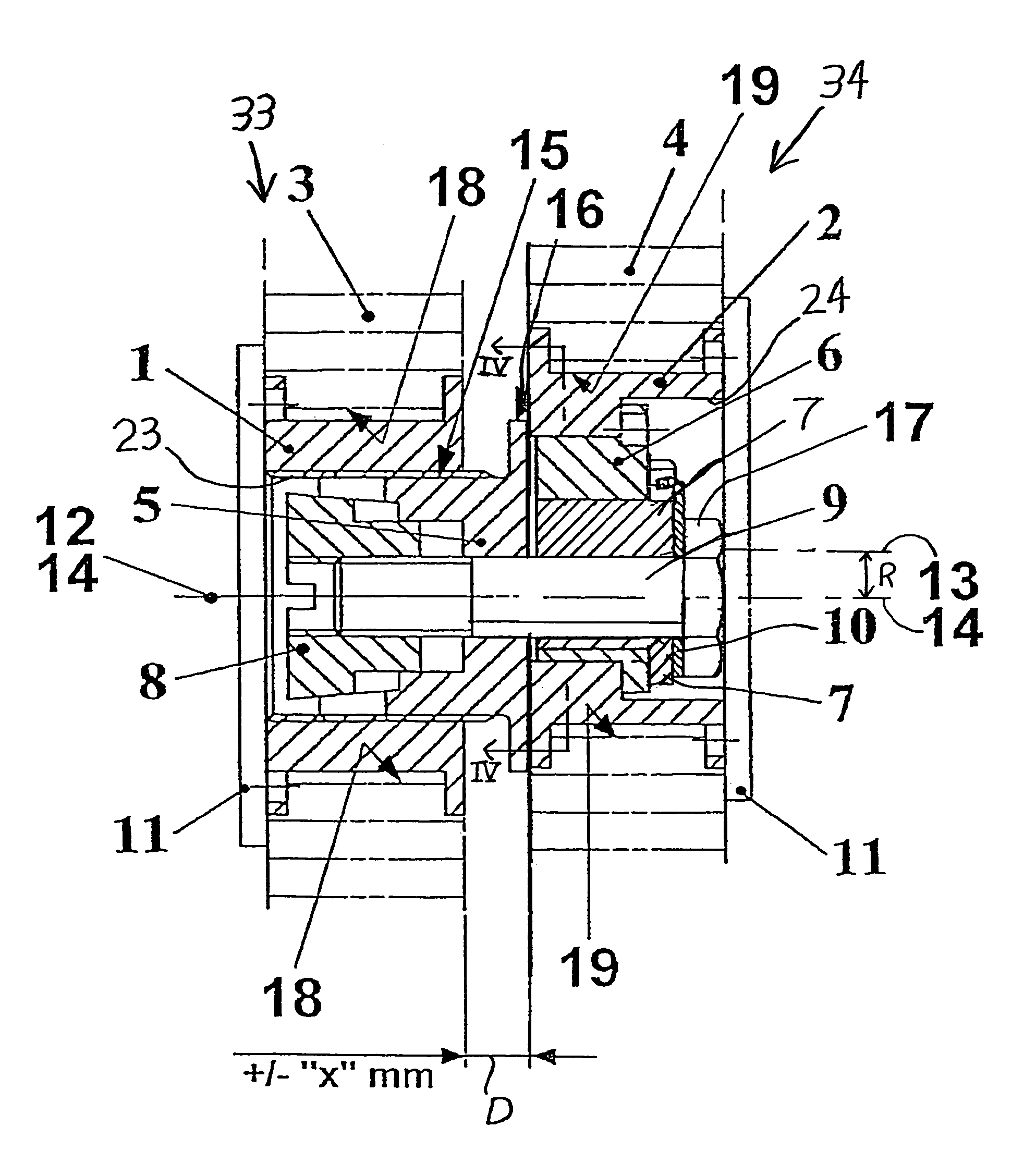
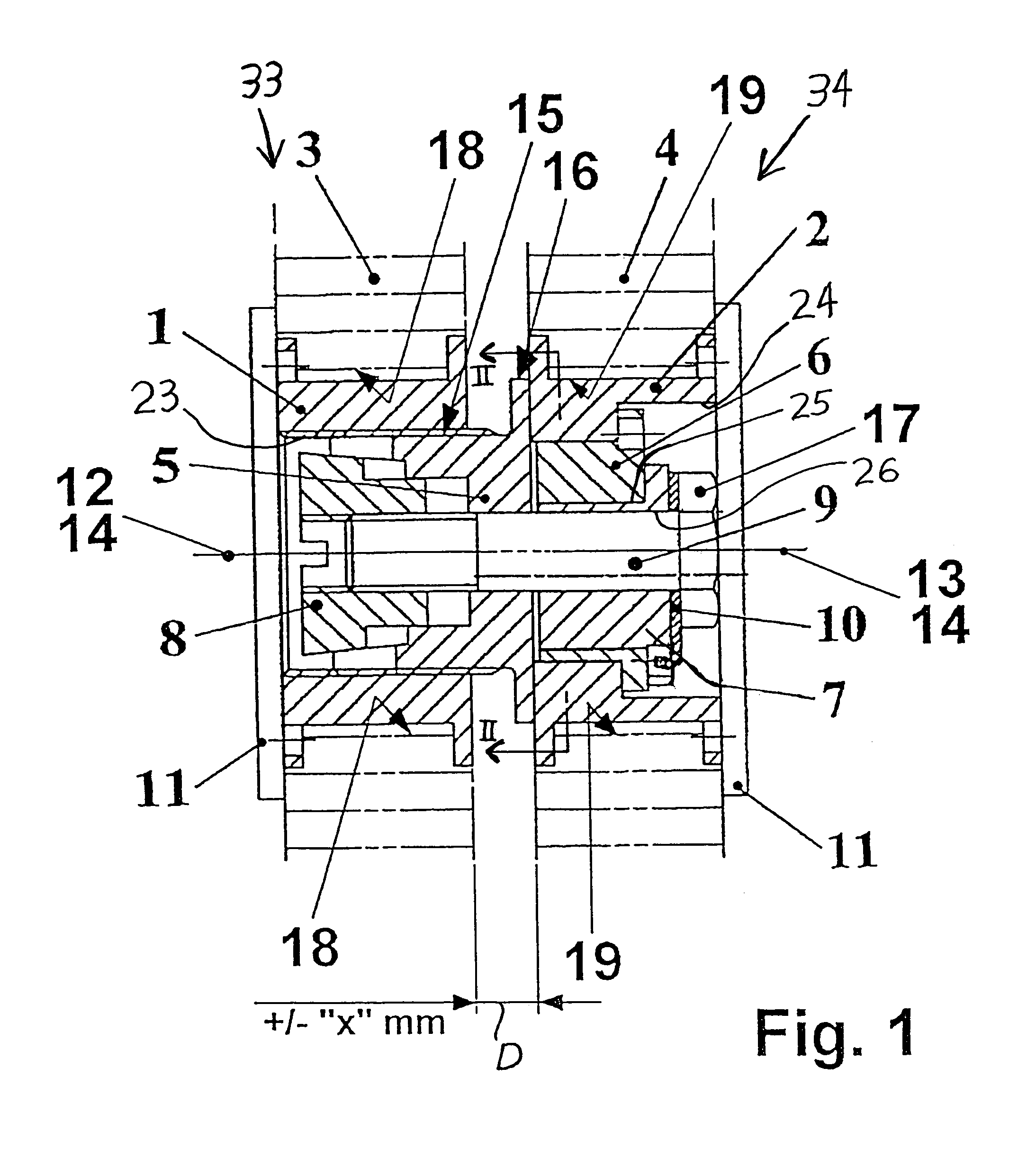
[0022]The inventive connection arrangement is for mechanically connecting a first component 33 with a second component 34, via an internally threaded first hole 23 provided in the first component 33 and an unthreaded second hole 24 provided in the second component 34. Depending on the material and structure of each component 33 and 34, the respective first and second holes 23 and 24 can be provided either directly in the material of the respective component, or in a further sleeve inserted and fixed into a larger opening in a component panel or body of the component. On the one hand, if the respective component 33 or 34 is made of a solid strong metal, then the threaded first hole 23 or the unthreaded second hole 24 can be provided directly as a respective bored hole in the metal body of the respective component 33 or 34. On the other hand, if the body of the component 33 or 34 has a structure or consists of a material with insufficient strength for supporting and securing the inven...


PUM


Abstract

A connection arrangement accommodates misalignments in three dimensions, and achieves a positive fixed connection between two components. A threaded standoff with a first bolt hole therein is partially screwed into a threaded hole in the first component and protrudes to match the spacing distance between the components. Inner and outer eccentric disks are received and supported in a hole in the second component. The inner disk has an offset center relative to the outer disk, and has a second bolt hole offset from the inner disk's center. Rotating the two disks accommodates radial misalignments to bring the two bolt holes into alignment. A bolt shaft extends through the bolt holes. While a bolt head or nut at one end of the shaft bears against the eccentric disks, a clamping cone at the opposite end of the shaft is tightened to axially clamp the standoff against the second component, and to radially outwardly spread and clamp the standoff against the internal threading of the first hole in the first component. The first hole can be in a threaded sleeve secured in the first component, and the second hole can be in a clamping sleeve secured in the second component. The second hole may be a recessed stepped hole.

Description

PRIORITY CLAIM[0001]This application is based on and claims the priority under 35 U.S.C. §119 of German Patent Application 103 53 376.1, filed on Nov. 14, 2003, the entire disclosure of which is incorporated herein by reference.FIELD OF THE INVENTION[0002]The invention relates to a mechanical connection of two components to each other using a bolt, while allowing alignment compensation of alignment deviations between the two components, and achieving a form-locked positive play-free fixed connection.BACKGROUND INFORMATION[0003]Various different arrangements for achieving a positive form-locked and play-free mechanical connection between two components are known. Particularly, such known mechanical connections also allow for alignment compensation between the two components, but only with respect to two planes or in two dimensions or directions. In other words, the known mechanical connections allow for a compensation of mis-alignments along two axes, but not along the third axis or ...

Claims


Application Information

Patent Timeline
Patent Type & Authority Patents(United States)
IPC IPC(8): F16D1/00F16B5/02
CPCF16B5/025Y10T403/556Y10T403/557Y10T403/7064Y10T403/7067Y10T403/7069Y10T403/75Y10T403/7066
Inventor STEINBECK, HERBERT
Owner DIEHL AIRCABIN
Why Eureka
Try Eureka