Speed transmission apparatus

Inactive Publication Date: 2006-05-02
DUPRIEZ CHARLES LOUIS
View PDF8 Cites 5 Cited by
  • Summary
  • Abstract
  • Description
  • Claims
  • Application Information

AI Technical Summary

Benefits of technology

[0005]The aim of the present invention is to develop a speed transmission apparatus making it possible to modify the transmission ratio without discontinuity, between two selectable given limits, and without power limitation. Advantageously the transmission apparatus can be controlled manually or entirely automatically, or by combining the two modes.
[0015]According to one embodiment of the invention, the apparatus also comprises a second intermediate shaft arranged in the other one of the said first and second rotation transmissions, so as to be able to rotate about a fourth rotation axis, and a second electric motor brake which acts on the second intermediate shaft, whilst being capable of modifying a speed of rotation thereof, following commands received from the control means to which it is electrically connected. Preferentially, the first intermediate shaft and the second intermediate shaft have, in the absence of the motor brakes, different speeds of rotation, the motor brake acting on the fastest intermediate shaft is an alternator having coils, whose excitation can be varied in order to obtain a variable brake effect, and producing an electric current, and the motor brake acting on the slowest intermediate shaft is an electric motor, which is supplied by the electric current produced by the said alternator and which makes it possible to obtain a variable acceleration effect. This arrangement is particularly advantageous since it makes it possible to recover the energy developed by the braking of the first intermediate shaft and to use it for starting an electric motor which accelerates the second gear shaft, with the result of more effectively obtaining the required effect, that is to say a modification to the gear ratio.
[0019]According to a particular embodiment of the invention, the first rotary casing is arranged so as to be driven in rotation by the drive engine, thus serving as a driving input for the apparatus, and the double gear train is housed in the first rotary casing. In such an embodiment, the double gear train is enclosed in a single chamber and the apparatus is relatively compact.

Problems solved by technology

The drawback of this type of transmission is its discontinuity.

Method used


Image

  • Speed transmission apparatus
  • Speed transmission apparatus
  • Speed transmission apparatus

Examples


Embodiment Construction

[0024]In the various drawings, the identical or similar elements are designated by the same references.

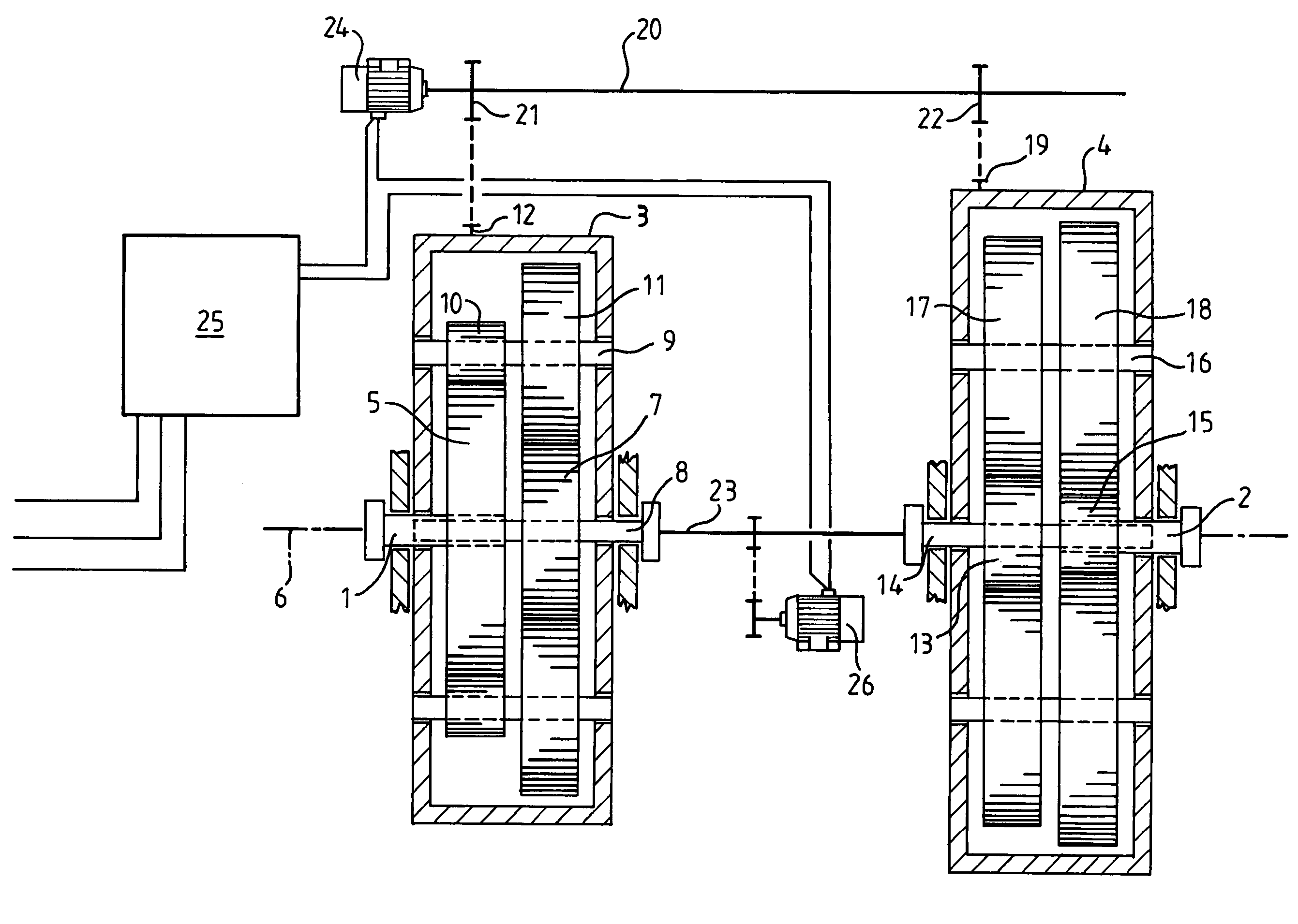
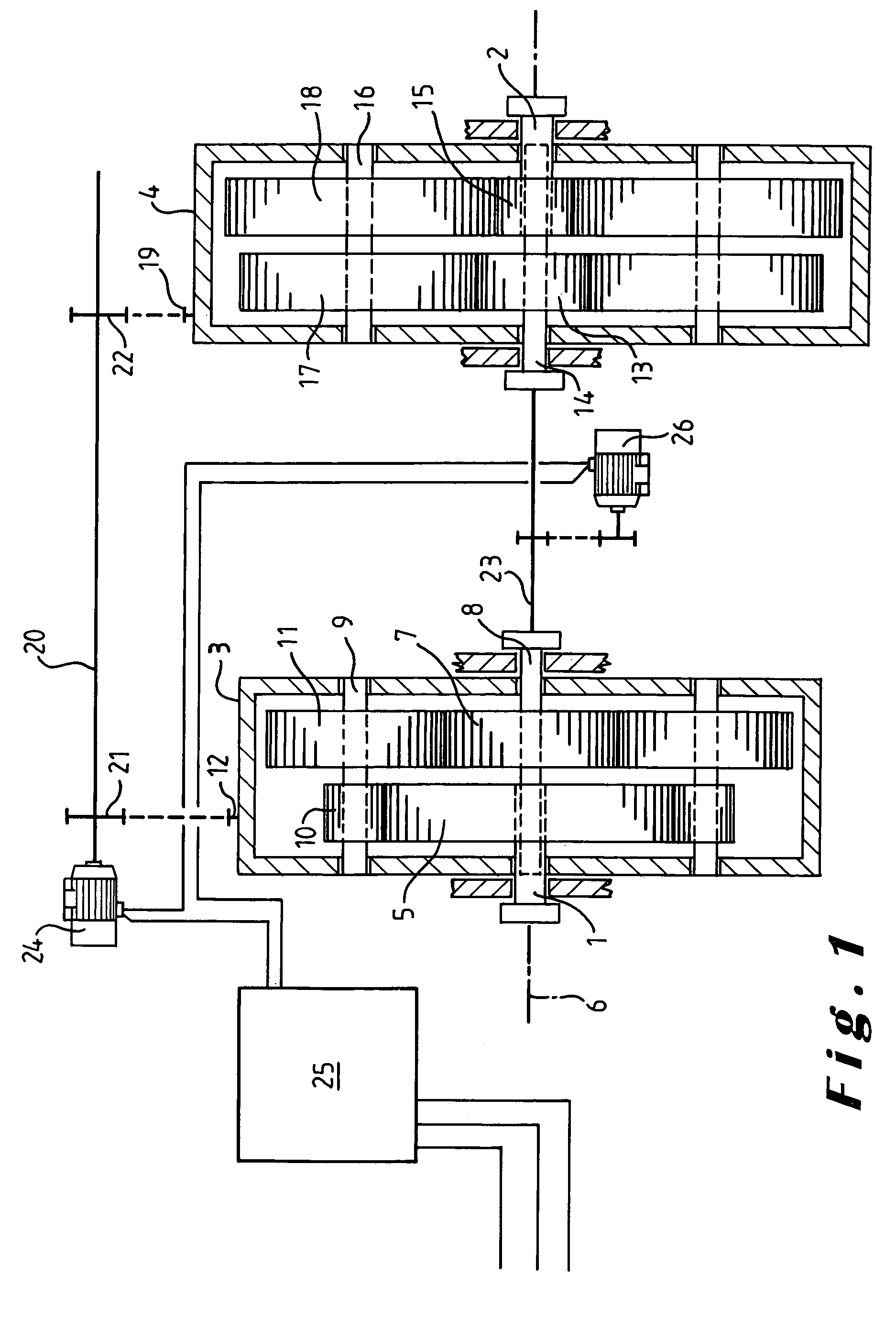
[0025]In FIG. 1, the transmission apparatus depicted is arranged between a normal drive engine, not shown, and coupled to an input shaft 1, and a normal drivable receiving device, not shown, and coupled to an output shaft 2.

[0026]The apparatus comprises a double epicyclic gear train which has a first epicyclic gear train housed in a first rotary casing 3 and a second epicyclic gear train housed in a second rotary casing 4. Each rotary casing, with its gear train, is a known system which can be found on the market for example under the name Redex epicyclic system (the firm Texrope, Industrial Transmission Company).

[0027]The first gear train comprises a first sun-carrier plate 5, mounted on the input shaft 1 so as to rotate with it, about its rotation axis 6, and a second sun-carrier plate 7, mounted on a interposed output shaft 8 so as to be able to rotate with it, about this same r...


PUM


Abstract

A speed transmission apparatus containing a first rotary crankcase, a double planetary gearset, a first rotation transmission arranged at an intermediate output of the first gearset, a second rotation transmission arranged at an intermediate input of the second gearset, a first intermediate shaft arranged in one of the first and second transmissions, a first electric compression brake acting on the first intermediate shaft and capable of modifying a rotational speed thereof, a computer electrically connected to the first compression brake, and an electrical connection capable of being provided between the first compression brake and a second compression brake whereof the effect is to accelerate the second intermediate shaft by the braking effect exerted on the first intermediate shaft by the first compression brake.

Description

BACKGROUND OF THE INVENTION[0001]The present invention relates to a speed transmission apparatus arranged between a drive engine and a drivable receiving device, for example a machine to be driven, industrial or agricultural, or the wheels of a motor car.[0002]At the present time this transmission takes place by means of a gearbox provided with a defined number of ratios. The drawback of this type of transmission is its discontinuity. It can take place only by successive jumps.[0003]In order to attempt to remedy this problem, there have already been provided, in the case of engines of low or medium power, transmission devices, known as continuous variators, which can however not be used for high powers, greater than approximately 40 continental HP (29.420 W).[0004]For engines with higher powers, the use of automatic gearboxes has been provided for, which make it possible to avoid manual actions for changing transmission ratios, but the aforementioned discontinuity remains.SUMMARY OF...

Claims


Application Information

Patent Timeline
IPC IPC(8): F16H3/72F16H37/06F16H3/56F16H3/66H02P15/00
CPCF16H3/72F16H3/56F16H3/727Y10T477/23F16H2037/104Y10T477/26F16H2037/103
Inventor DUPRIEZ, CHARLES LOUIS
Owner DUPRIEZ CHARLES LOUIS
Why Eureka
Try Eureka