Autonomous anchoring method and system for foundations of offshore structures

a technology of offshore structures and anchoring methods, applied in artificial islands, instruments, construction, etc., to achieve the effects of low installation costs, minimal need for maritime resources, and low anchoring speed

Active Publication Date: 2018-06-28
DRACE GEOCISA SA
View PDF2 Cites 3 Cited by
  • Summary
  • Abstract
  • Description
  • Claims
  • Application Information

AI Technical Summary

Benefits of technology

[0016]Anchoring speed can be modified by varying the filling rate of the cells of the foundation with seawater.
[0017]Despite the random nature of the factors involved in the anchoring method, this system is autonomous to the extent that it is capable of making decisions in a systematic way, thus providing repeatability. This way, the floating object is capable of managing its own commissioning and, therefore, necessary maritime resources, such as anchoring support, are minimal and installation costs are also lower.
[0018]The system also provides reliability to foundation installation operations through the definition of quality parameters (operational threshold values) that the system itself ensures are not exceeded. This is the very reason it is an autonomous system that does not need the support of high-level maritime resources. The floating object itself can behave like a vessel.

Problems solved by technology

The problem that arises when it comes to anchoring foundations for offshore structures, which have to be completely submerged several meters below sea level consists in being able to control the final stage of anchoring, i.e., from the moment the caisson is totally submerged until it smoothly settles in its final location without having to place people on top of the caisson in order to control the maneuver and without using cranes or similar means for supporting the caisson throughout the progress of the proceedings, since it is a self-anchoring process.

Method used


Image

  • Autonomous anchoring method and system for foundations of offshore structures
  • Autonomous anchoring method and system for foundations of offshore structures
  • Autonomous anchoring method and system for foundations of offshore structures

Examples


Embodiment Construction

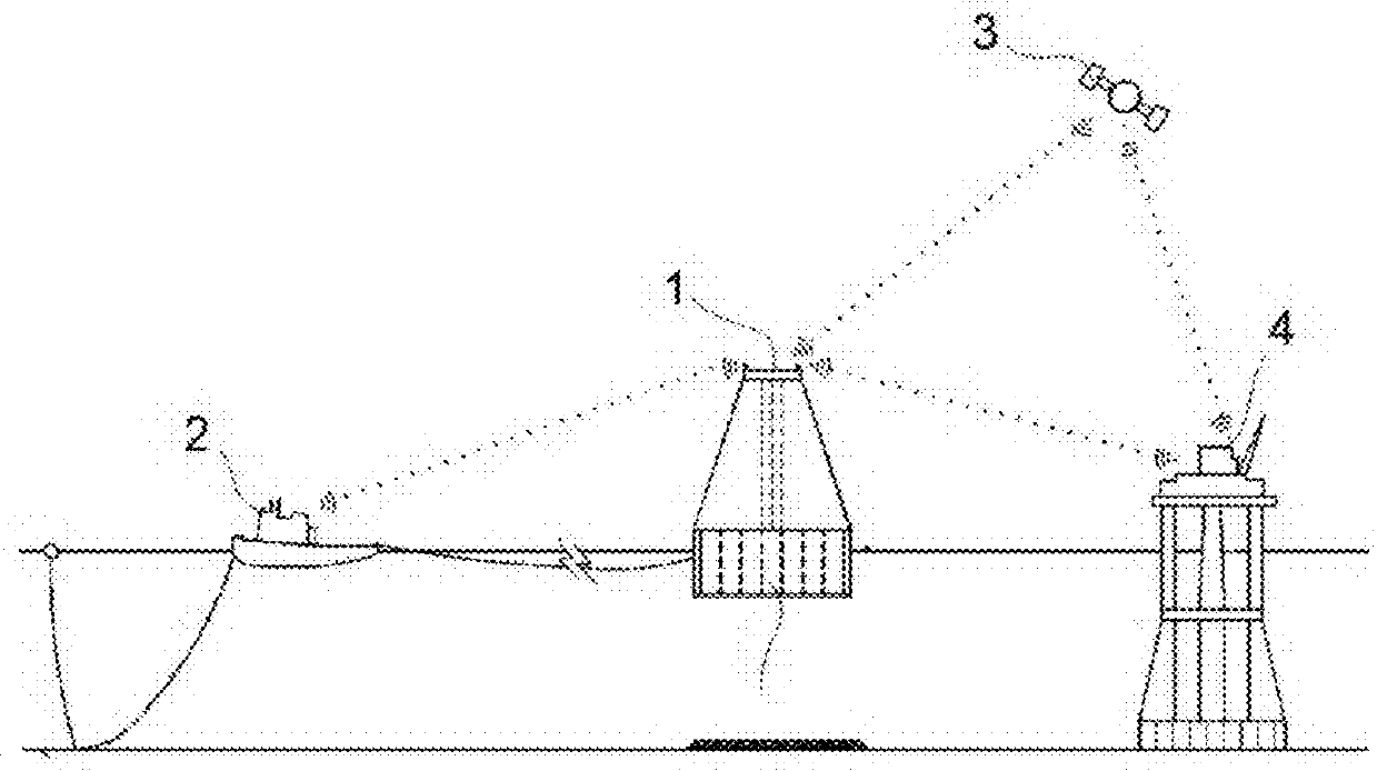
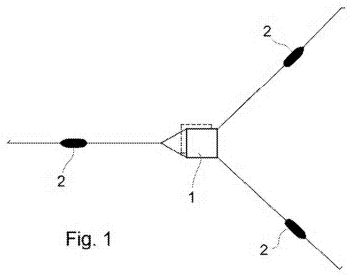
[0089]The proposed system for anchoring integrates its different elements into the equipment comprising the assembly of the same: tugboats (2), foundation to be anchored (1), base platform or fixed point of reference (4) and positioning network (3): see FIG. 2).

[0090]The user interface consisting of a command control server or SCADA (Supervisory Control And Data Acquisition) system is installed in the tugboats (2), which system enables remote visualization, monitoring and control of the process. It is a closed loop system, i.e., it adjusts the control through feedback of the output signal. An 8-port switch, two modems for wireless communication and at least two CPUs and auxiliary screens are also installed in the tugboats (2), which enable the visualization of the status of the process variables by means of an interface. This interface has particular tabs for visualizing the position of the element to be installed, filling level of the cells, alarms, electrical parameters, tension i...


PUM


Abstract

A method for the autonomous anchoring of foundations for offshore structures consisting of a self-floating concrete caisson manufactured in a floating dock, capable of being towed to their final location, provided with internal vertical cells, which are divided into cells that are interconnected with each other and equipped with emptying and filling devices that allow the regulation of the ballast level for anchoring when they are filled with seawater. This method comprises the following stages: constraining the foundation, fastening and mooring by at least three tugboats pulling radially on the foundation to be anchored from at least 3 different directions; connecting the different sensors needed for controlling the operation with a control unit; gradual and controlled sinking of the foundation until it reaches its position of installation on the seabed; and final ballasting of the foundation.

Description

BACKGROUND OF THE INVENTIONField of the Invention[0001]The present invention relates to a method for the autonomous anchoring of foundations for offshore structures, which allows automatic control of the positioning of the structure by means of a system using sensor, control and communication modules.Description of Related Art[0002]Gravity foundations of offshore structures can be subdivided into two groups, which are distinguished by the way in which they are transported to their final emplacement, i.e., floating and non-floating foundations. Floating foundations differ from non-floating foundations in that they have the capacity of being towed, thus reducing the costs involved in this stage of the project. Currently, both types of foundations require special means, with a great capacity for load handling, in order to carry out their anchoring and final positioning. In other words, they are not autonomous in their functional transition between floating element, during the transport...

Claims


Application Information

Patent Timeline
Patent Type & Authority Applications(United States)
IPC IPC(8): E02D27/52E02B17/02
CPCE02D27/52E02B17/02E02D2600/10E02B17/025E02B2017/0039E02B2017/0069E02D27/42G01S19/14G01S19/43G01S19/01
Inventor POLIMON OLABARRIETA, CARLOS JES SEGUIAGARAY GARCIA, MIGUELMOLINA SANCHEZ, RAFAELCABRERIZO MORALES, MIGUEL ANGELRODRIGUEZ MORENO, ALBERTO
Owner DRACE GEOCISA SA
Why Eureka
Try Eureka