Fiber closure system

Active Publication Date: 2006-05-02
PREFORMED LINE PROD CO
View PDF41 Cites 97 Cited by
  • Summary
  • Abstract
  • Description
  • Claims
  • Application Information

AI Technical Summary

Benefits of technology

[0007]In accordance with yet another aspect of the invention, a universal fiber organizer is provided comprising a top organizer bar, a bottom storage bar, a fiber splicing tray, a tray restraint clip, and a fiber storage strap. The top organizer bar serves as the structure to support the fiber splicing trays. The bottom storage bar serves as a floor for storing loose fiber prior to transitioning the fiber into the splicing trays. The splice trays can be individually accessed without disrupting the other trays contained in the enclosure. The volume of space required to store the loose fiber can be enlarged or reduced per the customers requirements and a removably connected design allows for open access to the fiber storage area.
[0008]In accordance with yet another aspect of the invention, a tray restraint clip is provided for retaining a fiber splice tray. The geometry of the tray restraint clips are such that the clips can interlock with one another as they are stacked whereby the fiber tray capacity is increased in the enclosure. The clips can also slide together in one direction and small locking bumps are provided for engaging into locking slots which lock adjacent clips together. The locking feature is not permanent and can be overcome if desired in order to remove the clip. The interloc

Problems solved by technology

These prior enclosures are satisfactory to a greater or lesser degree but often have certain defects which make

Method used


Image

  • Fiber closure system
  • Fiber closure system
  • Fiber closure system

Examples


Embodiment Construction

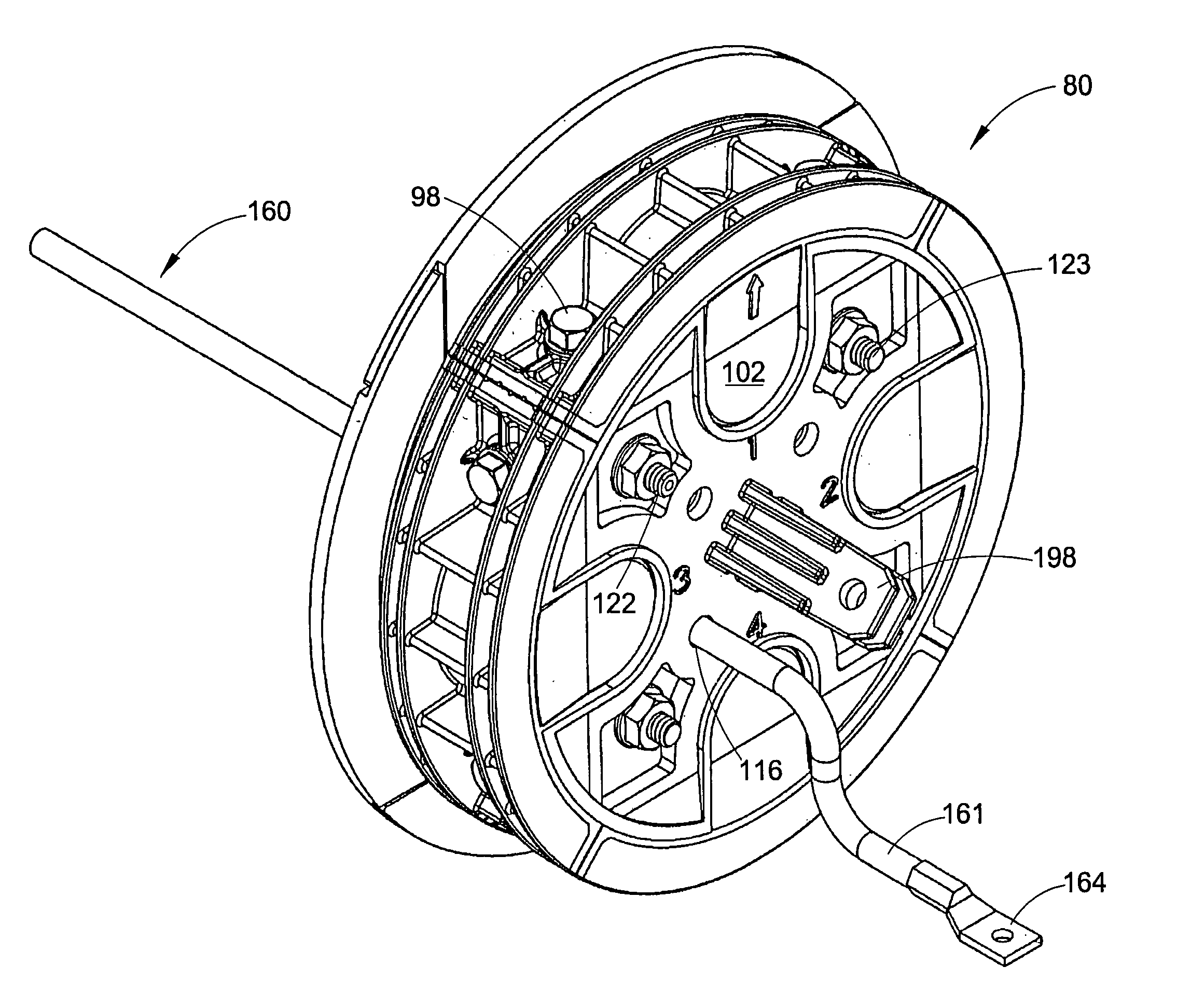
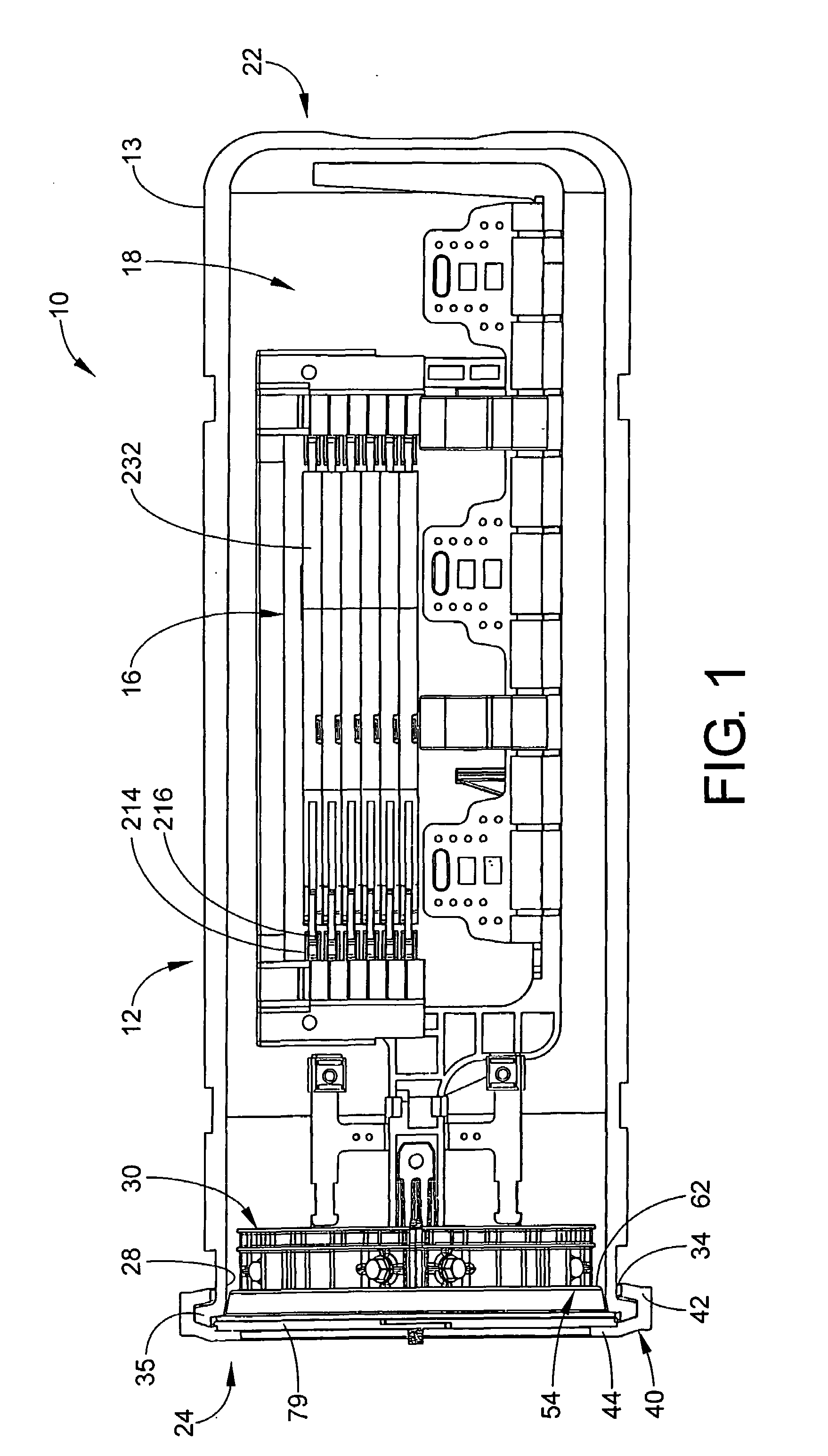
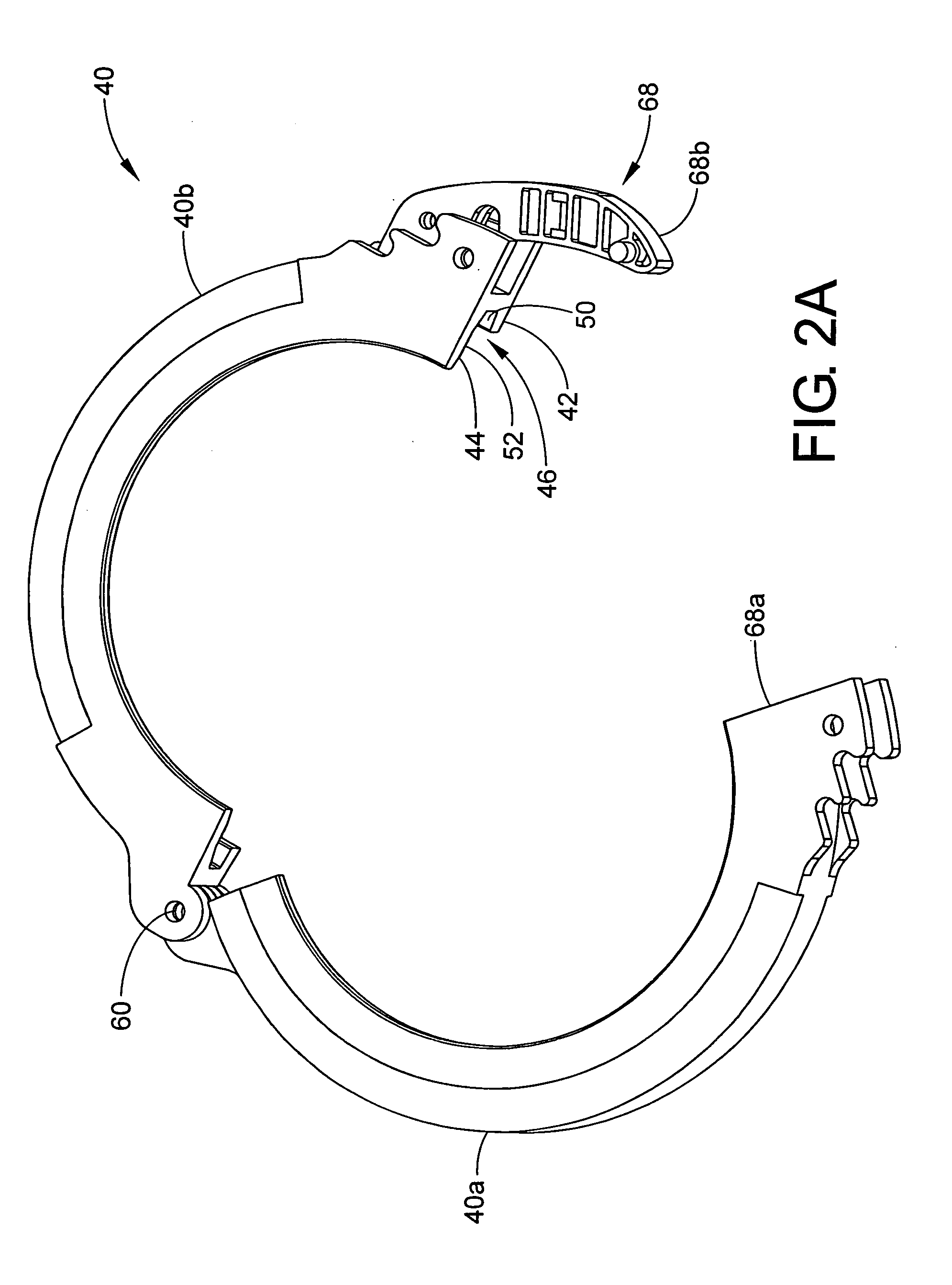
[0033]Referring now to the drawings wherein the showings are for the purposes of illustrating the preferred embodiments of the invention only and not for purposes of limiting the same, the overall arrangement of the preferred construction of the splice case 10 can best be understood by reference to FIG. 1. As illustrated therein, a main outer housing or dome 12 of splice case 10 comprises a housing enclosure that houses and encloses a splice tray support assembly or fiber organizer 16. The housing 12 is generally formed as a cylindrical tube or domed shell with an interior chamber 18 closed at one end 22 including a rib structure (not illustrated) around its exterior. The housing 12 includes an open end 24 opposite the closed end 22. The open end 24 of the cylindrical tube or housing 12 is closed by a circular end plate member 80 and a collar 40 that is releasably and sealingly engaged with the main housing 12 in a manner to be described hereinafter.

[0034]Although the housing 12 bod...


PUM


Abstract

A cable splice enclosure assembly for enclosing and storing cable splices includes a housing member having a closed end and an open end which defines a storage chamber therebetween. An end plate is received in the open end. The end plate is axially spaced from the closed end. The end plate includes an end plate body and a plurality of selectively removable cable caps for accessing individual cables passing through openings defined by the end plate. A plurality of sealing walls are selectively positionable in the openings for blocking the openings when not being used to receive the cables in the openings. A piercable grommet is disposed in a further opening found in the end plate for selectively receiving a ground or other electrical wire therethrough to seal the wire with the end plate.

Description

[0001]This application claims the benefit of U.S. Provisional Application Ser. No. 60 / 479,283, filed Jun. 18, 2003.BACKGROUND OF THE INVENTION[0002]The subject invention is directed to a waterproof cable splice enclosure assembly. Assemblies of the type under consideration are particularly suited for enclosing and housing fiber optic cables, and the invention will be described with particular reference thereto; however, the apparatus could equally well be used with other types of cables.[0003]Many different types of fiber optic cable enclosures are known in the prior art. These prior enclosures are satisfactory to a greater or lesser degree but often have certain defects which make them inconvenient to use or prevent them from being readily adaptable to changing environments and conditions. It is, accordingly, an object of the subject invention to provide a cable enclosure assembly that is easy to assemble, use, and maintain. The subject invention also provides a cable enclosure whi...

Claims


Application Information

Patent Timeline
IPC IPC(8): H02G3/06G02B6/44H02G3/22H02G15/013H02G15/117
CPCG02B6/4442G02B6/4455H02G15/117H02G15/013H02G3/22
Inventor GRUBISH, CHRISTOPHER STEPHENLATIMER, BRETT ALLENMILLER, KEITH ALAN
Owner PREFORMED LINE PROD CO
Why Eureka
Try Eureka