Fixing device including a screw arranged with clearance in a fixing hole, and a weight measuring apparatus using the same

a fixing hole and screw technology, applied in the direction of pedestrian/occupant safety arrangement, instruments, tractors, etc., can solve the problems of conspicuous reduction of detection accuracy and tendency to friction in vertical motion

Inactive Publication Date: 2006-05-02
PANASONIC CORP
View PDF10 Cites 51 Cited by
  • Summary
  • Abstract
  • Description
  • Claims
  • Application Information

AI Technical Summary

Problems solved by technology

However, even if the conventional weight measuring apparatus itself has high accuracy, when a load is applied, friction tends to occur in a vertical motion because of a positional deviation or a surface slope at a fixing section.
As a result, detecting accuracy is conspicuously reduced because of a transmission loss, which is caused by the friction, of the load.

Method used


Image

  • Fixing device including a screw arranged with clearance in a fixing hole, and a weight measuring apparatus using the same
  • Fixing device including a screw arranged with clearance in a fixing hole, and a weight measuring apparatus using the same
  • Fixing device including a screw arranged with clearance in a fixing hole, and a weight measuring apparatus using the same

Examples


first exemplary embodiment

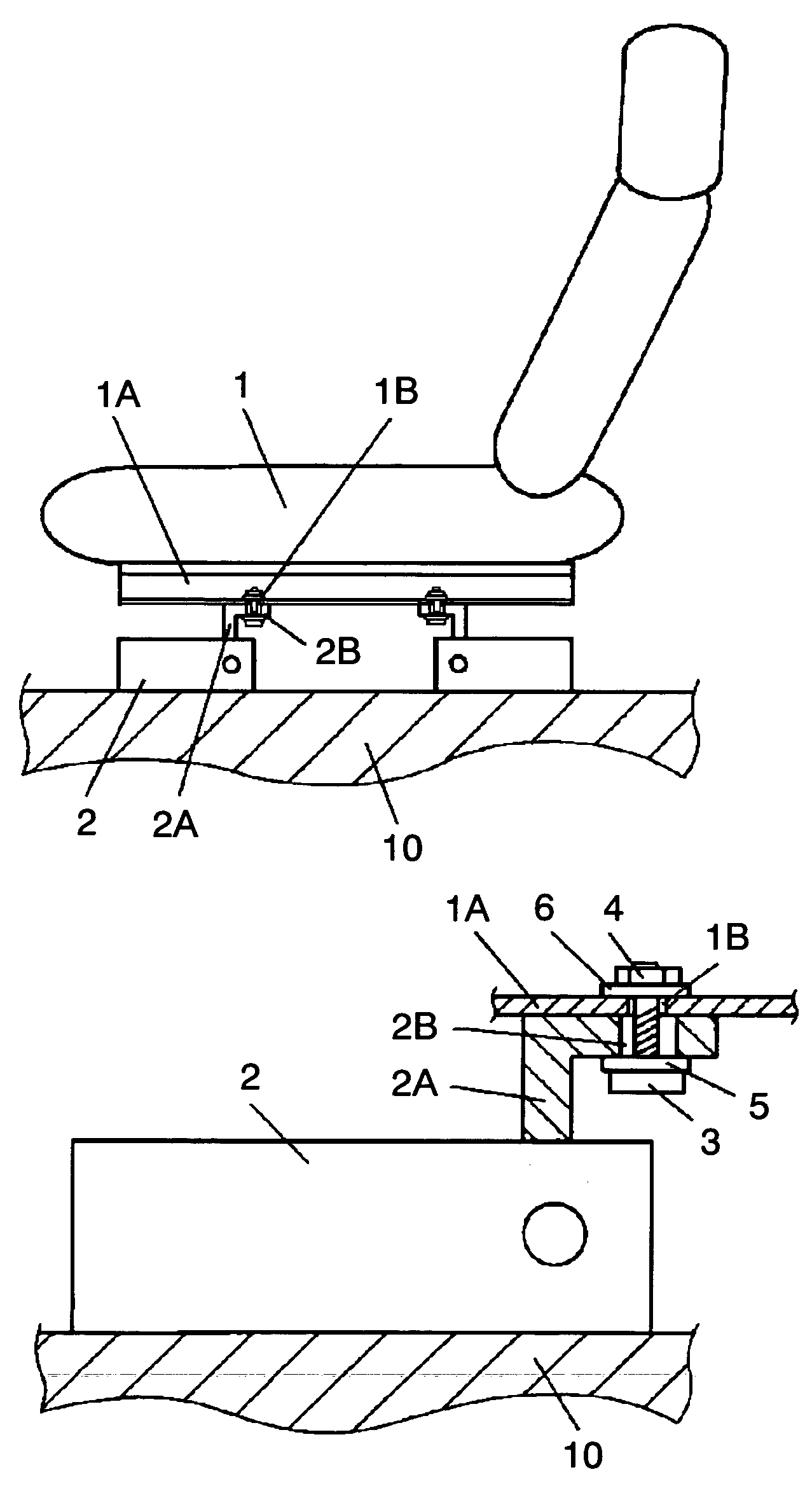
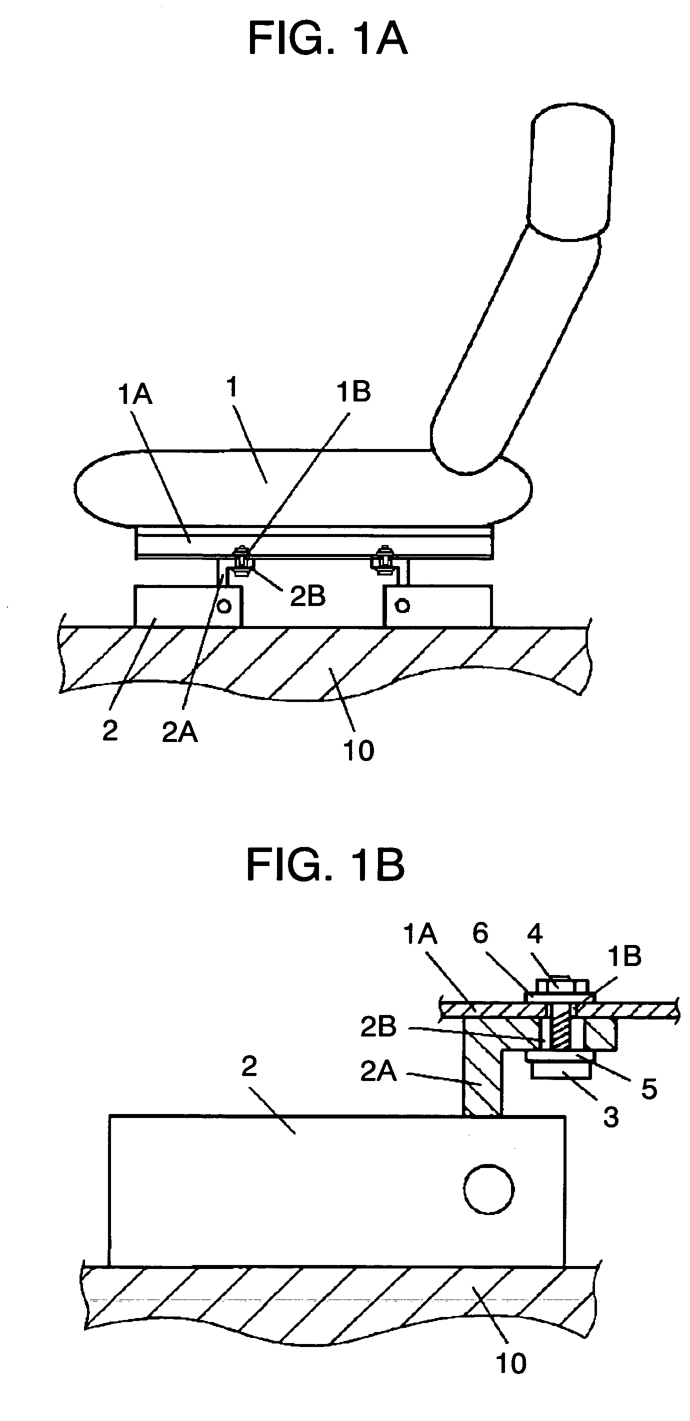
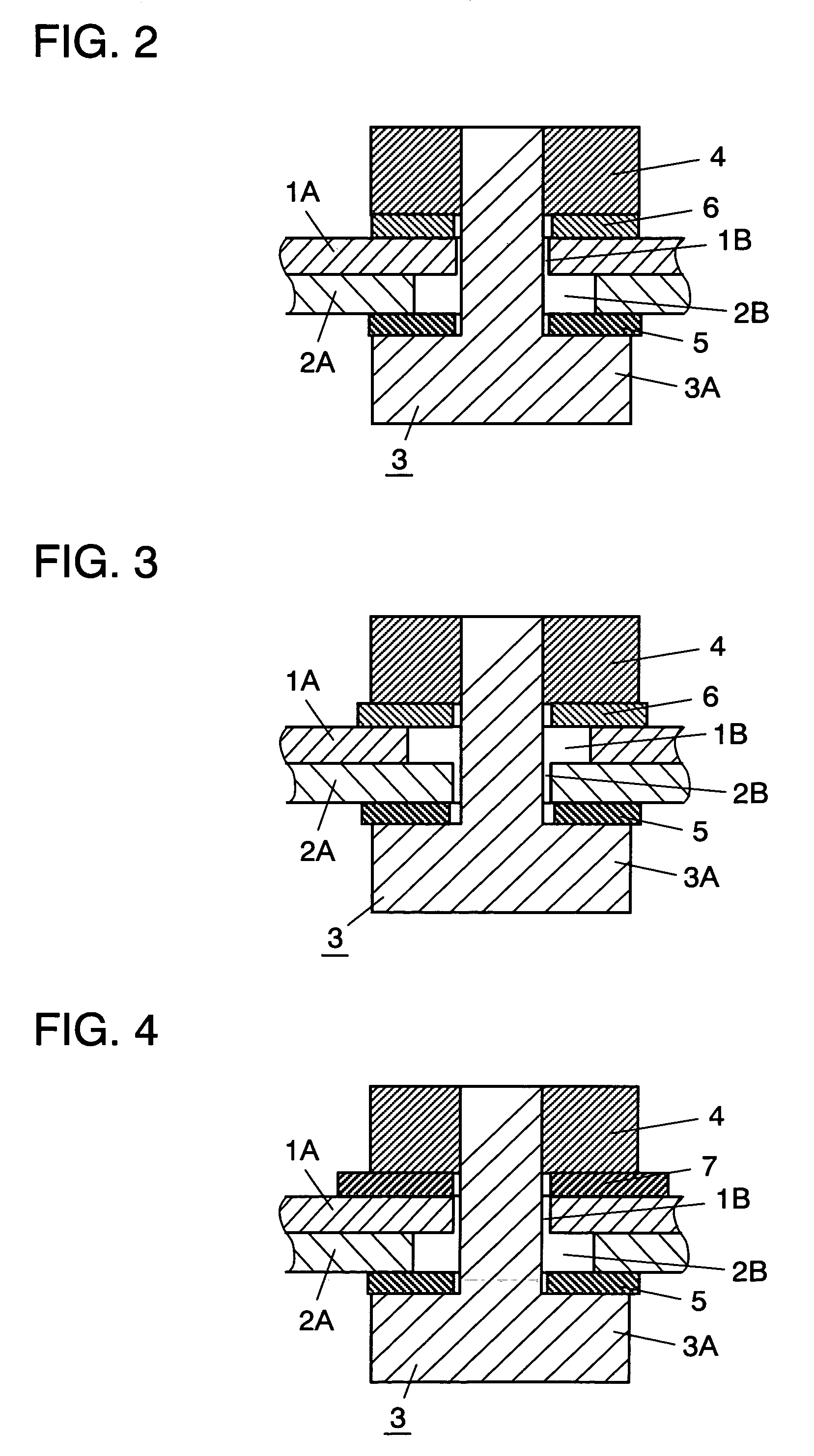
[0021]FIG. 1A is an overall view of a seat weight measuring apparatus in accordance with the first exemplary embodiment of the present invention. FIG. 1B shows a structure of a fixing device in accordance with the first exemplary embodiment of the present invention. FIG. 2 is a sectional detail view of the fixing device. As shown in FIGS. 1A and 1B, seat 1 for a vehicle (hereinafter referred to as “seat 1”) is fixed to weight measuring machine 2 through first fixing section 1A (hereinafter referred to as “fixing section 1A”) and second fixing section 2A (hereinafter referred to as “fixing section 2A”). Fixing section 1A has first fixing hole 1B (hereinafter referred to as “fixing hole 1B”), and fixing section 2A has second fixing hole 2B (hereinafter referred to as “fixing hole 2B”). Screw 3 penetrates through fixing holes 1B and 2B, and is tightened with nut 4 via spacers 5 and 6, so that fixing section 1A is fixed to fixing section 2A. Spacer 6 is placed between nut 4 and fixing s...

second exemplary embodiment

[0029]FIG. 4 is a sectional detail view of a fixing device in accordance with the second exemplary embodiment of the present invention. This embodiment differs from the first embodiment in that elastic body 7 instead of spacer 6 is inserted between fixing section 1A and nut 4. Elastic body 7 is made of rubber, metal mesh, and resin having viscoelasticity or the like. The structures other than elastic body 7 are identical with those shown in FIG. 2 of the first embodiment.

[0030]An operation of the fixing device is described hereinafter. Similar to the first embodiment, second fixing hole 2B (hereinafter referred to as “fixing hole 2B”) has a clearance bigger than an assembly tolerance of first fixing hole 1B (hereinafter referred to as “fixing hole 1B”) and fixing hole 2B. Therefore, even when a positional deviation occurs, fixing hole 1B is not forced to be fixed to fixing hole 2B. As a result, a transmission loss caused by a twist is not generated, so that detecting accuracy is not...

third exemplary embodiment

[0033]FIG. 7 is a sectional detail view of a fixing device in accordance with the third exemplary embodiment of the present invention. The third embodiment differs from the first embodiment in that bushing 8 is inserted in first fixing hole 1B (hereinafter referred to as “fixing hole 1B”). Bushing 8 is smaller than fixing hole 1B in diameter, and thicker than first fixing section 1A. Other structures are identical with those shown in FIG. 2 of the first embodiment. Bushing 8 is made of metal, resin material, ceramic material or the like, which have certain mechanical strengths.

[0034]An operation of the fixing device is described hereinafter. Similar to the first embodiment, fixing hole 1B has a clearance bigger than an assembly tolerance of fixing hole 1B and fixing hole 2B. Therefore, even when a positional deviation occurs, fixing hole 1B is not forced to be fixed to fixing hole 2B. As a result, a transmission loss caused by a twist is not generated, so that detecting accuracy is ...


PUM


Abstract

According to a fixing device of the present invention, a screw penetrates through a first fixing hole of a first fixing section and a second fixing hole of a second fixing section to be coupled with a weight measuring machine, and is tightened with a nut, so that the first fixing section is fixed to the second fixing section. In addition, at least one clearance of the first fixing hole and the second fixing hole is configured to be bigger than an assembly tolerance of the two fixing holes. Using this structure, the fixing device, which can accommodate constructive variations of the fixing section of the weight measuring machine and maintain excellent detecting accuracy, and a weight measuring apparatus using the same, can be provided.

Description

TECHNICAL FIELD[0001]The present invention relates to a fixing device for fixing a weight measuring machine which measures weight of an object, and a weight measuring apparatus using the same.BACKGROUND ART[0002]Recently, to improve efficiency of a safety system of a vehicle, a method for measuring weight of an occupant, e.g., a crew member or a passenger, of the vehicle using a seat weight measuring apparatus has been under development for controlling motion of the safety system. The safety system mentioned above denotes a seat belt, an airbag or the like. For example, Japanese Patent Unexamined Publication H11-1153 discloses weight measuring apparatuses which are positioned at four corners of seat rails and measure seat weight to determine the weight of an occupant.[0003]However, even if the conventional weight measuring apparatus itself has high accuracy, when a load is applied, friction tends to occur in a vertical motion because of a positional deviation or a surface slope at a...

Claims


Application Information

Patent Timeline
Patent Type & Authority Patents(United States)
IPC IPC(8): B60R21/16G01G21/00G01G19/12B60N2/00B60N2/90B60R21/01B60R21/015B60R22/46G01G19/414G01G19/52
CPCB60N2/002F16B5/025B60R21/01516G01G19/4142Y10S177/09
Inventor SAITO, KIYOSHIKAWASAKI, SHUSAKUYOSHIUCHI, SHIGEHIROTANAKA, TSUYOSHI
Owner PANASONIC CORP
Why Eureka
Try Eureka