Terminating resistor device and a method for testing a terminating resistor circuit

a terminating resistor and resistor circuit technology, applied in the direction of pulse technique, line-transmission details, baseband system details, etc., can solve the problems of difficult discrimination between faults in decoder circuits and resistance value measurements of terminating resistor circuits, and achieve enhanced test accuracy.

Inactive Publication Date: 2006-05-02
RENESAS ELECTRONICS CORP
View PDF7 Cites 18 Cited by
  • Summary
  • Abstract
  • Description
  • Claims
  • Application Information

AI Technical Summary

Benefits of technology

[0012]An object of the present invention to overcome the drawbacks of the foregoing prior-art terminating resistor device and test method is to provide a terminating resistor device and a method for testing a terminating resistor circuit, by which the accuracy of test is enhanced.
[0013]A terminating resistor device according to the present invention comprises a terminating resistor circuit comprising a plurality of resistor elements, wherein a terminating resistance value can be changed by controlling the plurality of resistor elements, and a selecting circuit for test which can output a test signal to serially select one or a plurality of resistor elements out of the plurality of resistor elements. Through this arrangement of the terminating resistor device, the resistance value of the terminating resistor circuit can be test effectively.
[0014]The above terminating resistor device further comprises a control circuit which outputs a control signal to control the resistance value of the terminating resistor circuit. The selecting circuit for test is connected between the control circuit and the terminating resistor circuit in a circuitry arrangement. It is preferable that the selecting circuit for test selectively outputs the control signal from the control circuit or the test signal to the terminating resistor circuit. Through this arrangement, the test signal and the control signal can be sent effectively to the terminating resistor circuit. Moreover, the above selecting circuit for test, preferably, can output a signal input from the control circuit to its scan output in order to test the control circuit. Through this arrangement, discrimination can be made between a fault in the control circuit and a fault in the terminating resistor circuit. The selecting circuit for test is preferably a MUXSCANFF circuit comprising a plurality of flip-flop circuits. Through this arrangement, the control circuit and the terminating resistor circuit can be test effectively.
[0015]In the above terminating resistor device, preferably, the selecting circuit for test outputs the test signal to serially select a different resistor element out of the plurality of resistor elements. Through this arrangement, the resistance value of the terminating resistor circuit can be test effectively.
[0016]In the above terminating resistor device, preferably, the test signal serially selects one or two resistor elements out of the plurality of resistor elements and sets the selected one or two resistor elements ON. Through this arrangement, the resistance value of the terminating resistor circuit can be test effectively.
[0019]Also, the present invention provides a method for testing a terminating resistor circuit comprising a plurality of resistor elements, wherein a terminating resistance value can be changed by controlling the plurality of resistor elements. The method comprises the steps of: (a) selecting one or a plurality of resistor elements out of the plurality of resistor elements; (b) detecting the resistance value of the one or plurality of resistor elements selected; (c) selecting one or a plurality of resistor elements different from the one or plurality of resistor elements selected; (d) detecting the resistance value of the one or a plurality of resistor elements selected in the step (c). By the method built as above, the resistance value of the terminating resistor circuit can be test effectively.

Problems solved by technology

Therefore, the resistance value measurements of the terminating resistor circuit are susceptible to measurement errors.
Moreover, because a signal for test is input via the decoder circuit to the terminating resistor circuit 101, it is difficult to discriminate between a fault in the decoder circuit 104 and a fault in the terminating resistor circuit 101.

Method used


Image

  • Terminating resistor device and a method for testing a terminating resistor circuit
  • Terminating resistor device and a method for testing a terminating resistor circuit
  • Terminating resistor device and a method for testing a terminating resistor circuit

Examples


Embodiment Construction

[0029]Preferred embodiments of the present invention will be described hereinafter as examples of the embodiments in which the invention can be applied.

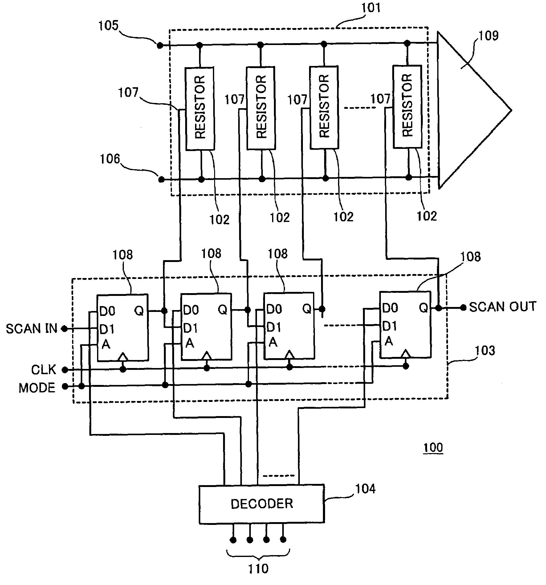
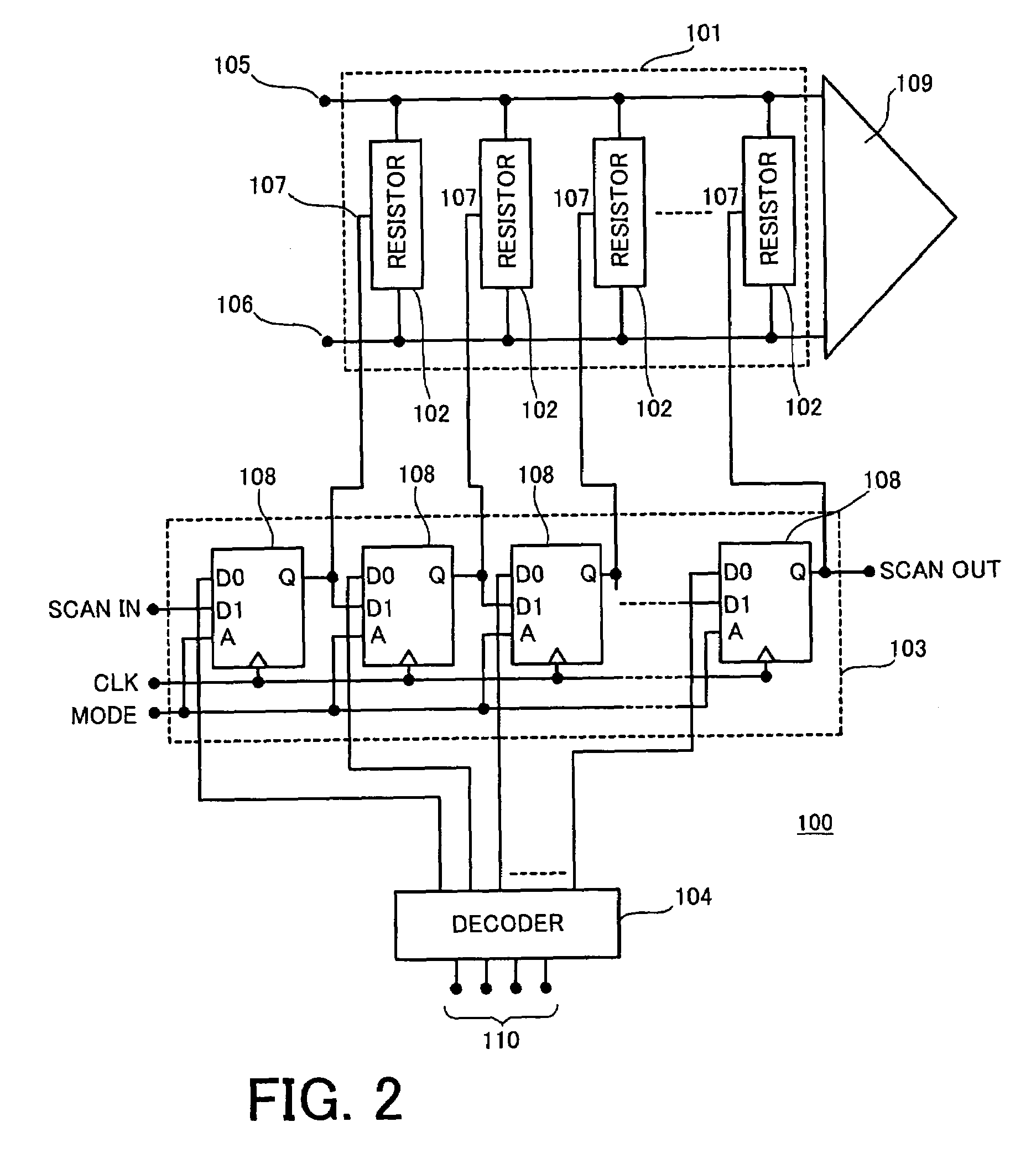
[0030]FIG. 2 is a block diagram showing a simplified configuration of a terminating resistor device 100 according to a preferred Embodiment 1 of the invention. FIG. 2 gives an example of the terminating resistor device installed in a receiving section of I / O circuitry. In FIG. 2, reference numeral 101 denotes a terminating resistor circuit comprising a plurality of resistor elements 102 to be controlled by signals 110 of several bits; 103 denotes a selecting circuit for test on the terminating resistor circuit 101; 104 denotes a decoder circuit for controlling a resistance value of the terminating resistor circuit 101. The selecting circuit 103 for test is connected between the decoder circuit 104 and the terminating resistor circuit 101 in a circuitry arrangement. A control signal from the decoder circuit 104 is input to the resisto...


PUM


Abstract

An object of the present invention is to provide a terminating resistor device and a testing method, by which the resistance value of a terminating resistor circuit can be test effectively. The test procedure starts with setting a MUXSCANFF circuit which functions as a selecting circuit in scan mode for test. Then, input a test signal to the scan input and / or clock input. Thereby, a particular resistor element for one bit only is set ON. By detecting the resistance value of this resistor element that has been set ON, it is test whether the one-bit resistance element conforms to manufacturing specification. Select another one of the one-bit resistor elements in order and test each one-bit resistor element, thereby testing all resistor elements.

Description

BACKGROUND OF THE INVENTION[0001]1. Field of the Invention[0002]The present invention relates to a terminating resistor device and a method for testing a terminating resistor circuit.[0003]2. Description of Related Art[0004]With a rapid advance of information technology (IT), transmission speed of data communicated on a transmission line is becoming higher and higher. To meet a variety of user needs, the type or the number of equipments that are connected to transmission lines varies, according to usage of computers or computer networks. As is known, some types of equipments that are connected to transmission lines are equipped with a variable terminating resistor device for impedance matching between a transmission line and the equipment. The equipments that are connected to transmission lines are, for example, a plurality of personal computers (PC). As for a serial or parallel interface which is used for connection between the computers, several specification are known. The comput...

Claims


Application Information

Patent Timeline
Patent Type & Authority Patents(United States)
IPC IPC(8): H03K17/16H04B3/02H04L25/02
CPCH04L25/0278H04L25/0292
Inventor NAKASHIMA, HIDEMIKURISU, MASAKAZU
Owner RENESAS ELECTRONICS CORP
Why Eureka
Try Eureka