
Image processing apparatus and its method, and image processing system and its control method

a technology of image processing apparatus and control method, which is applied in the direction of digital output to print units, instruments, digitally marking record carriers, etc., can solve the problems of increasing system load, inability to maintain image validity, and large number of duplication, so as to maintain image validity and reproducibility, and prevent degradation of throughput

Inactive Publication Date: 2006-05-02
CANON KK
View PDF4 Cites 12 Cited by
  • Summary
  • Abstract
  • Description
  • Claims
  • Application Information

AI Technical Summary

Benefits of technology

The present invention aims to solve problems in image processing by separating and processing different image regions with different rendering processing techniques to maintain image validity and reproducibility while improving throughput. The invention provides an image processing apparatus that can detect and separate image regions based on their color space and perform different rendering processing on them. This results in improved image quality and efficiency in processing large amounts of print information.

Problems solved by technology

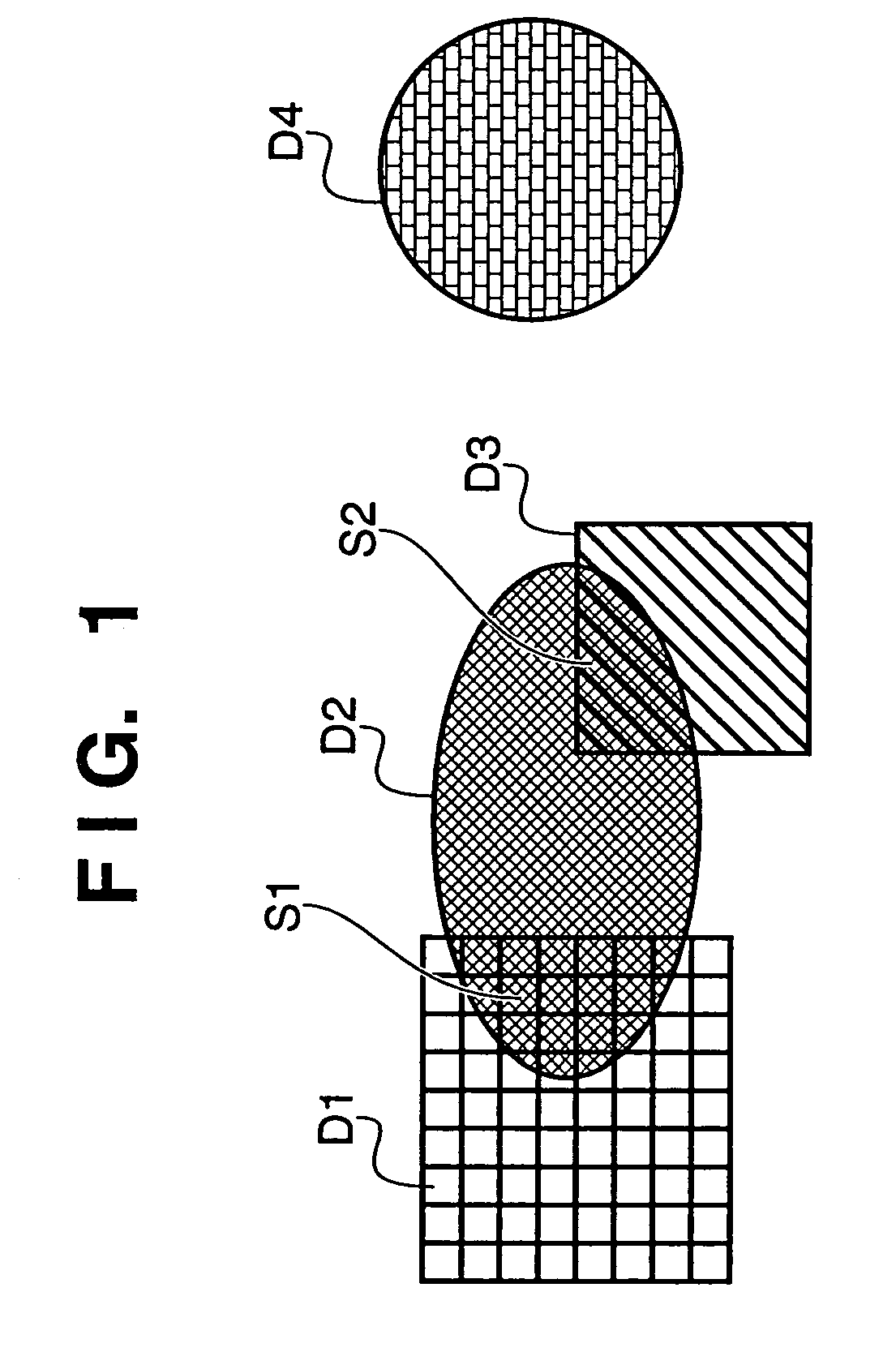
In a case where RGB representation data is inputted into the printing apparatus and converted to YMCK representation data, the color reproducibility of the object D4 which is not overlapped with the other objects, as shown in FIG. 1, can be approximately maintained by the performance of PDL (Page Description Language) However, regarding the objects D1 to D3 where regions S1 and S2 overlap with each other (in the case of duplication or transparency), in some cases, the validity of the image cannot be maintained even though the printing apparatus processes the above-described ROP code.
This problem frequently occurs as the number of duplication is large.
This processing increases the load on the system and degrades the throughput of the printing apparatus.

Method used


Image

  • Image processing apparatus and its method, and image processing system and its control method
  • Image processing apparatus and its method, and image processing system and its control method
  • Image processing apparatus and its method, and image processing system and its control method

Examples


Embodiment Construction

[0026]First, a color laser-beam printer as a printing apparatus to which the present invention is applicable will be described. Note that any apparatus may be employed as a printer to which the present invention is applicable as long as it is an image forming apparatus which scans a light beam thereby forms an image, such as a copier or a facsimile apparatus. Further, the printer is not limited to a color laser-beam printer but may be a monochrome laser-beam printer and further may be other types of printers such as an ink-jet printer and a thermal printer.

[Printing Apparatus]

[0027]FIG. 3 is a cross-sectional view showing an example of structure of a color laser-beam printer (hereinbelow simply referred to as a “color printer”).

[0028]The color printer shown in FIG. 1 having a resolution of 600 dpi prints a color image on a print sheet based on data representing color components respectively with 8 bits. The color printer inputs print information including print data (character code,...


PUM


Abstract

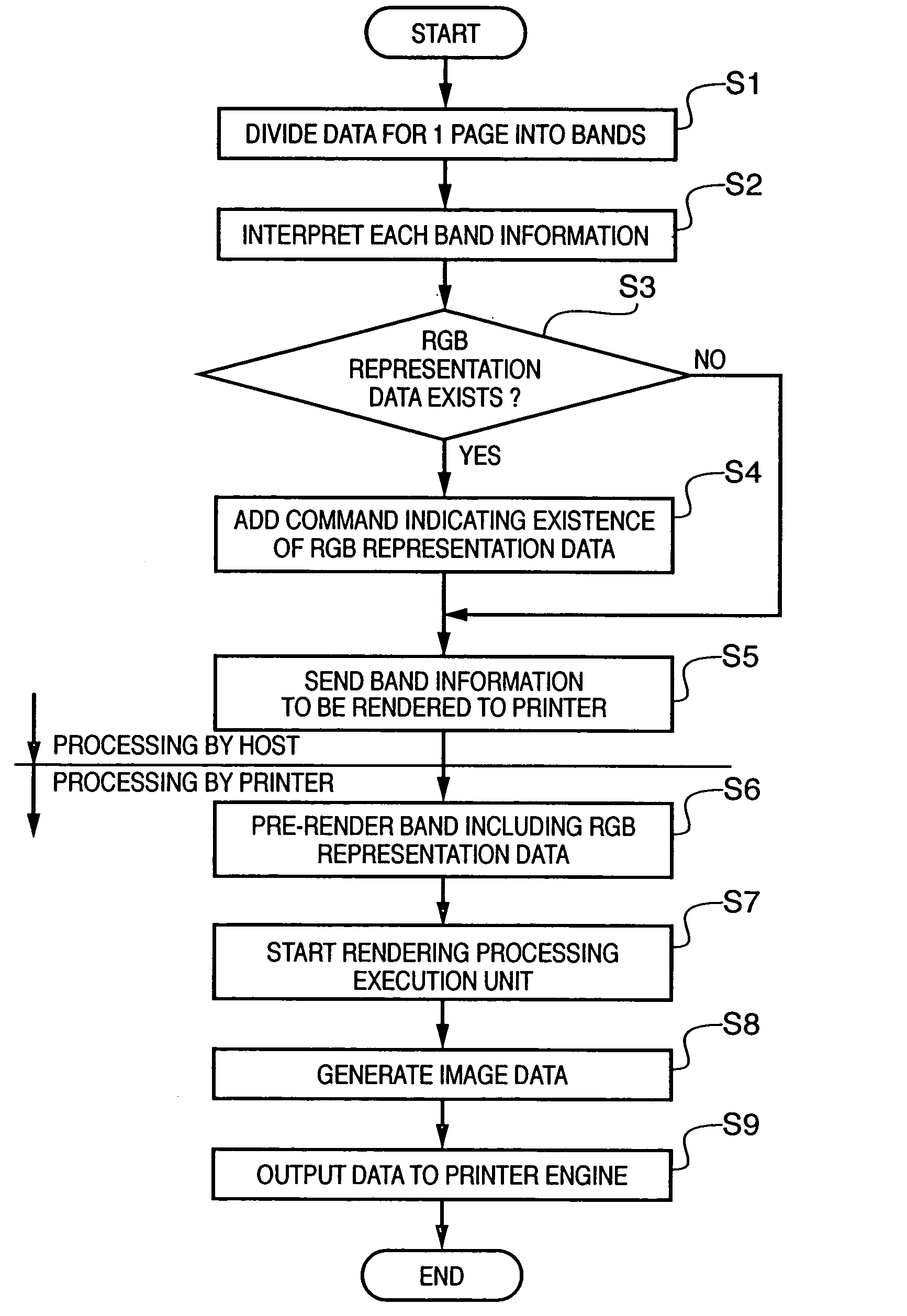
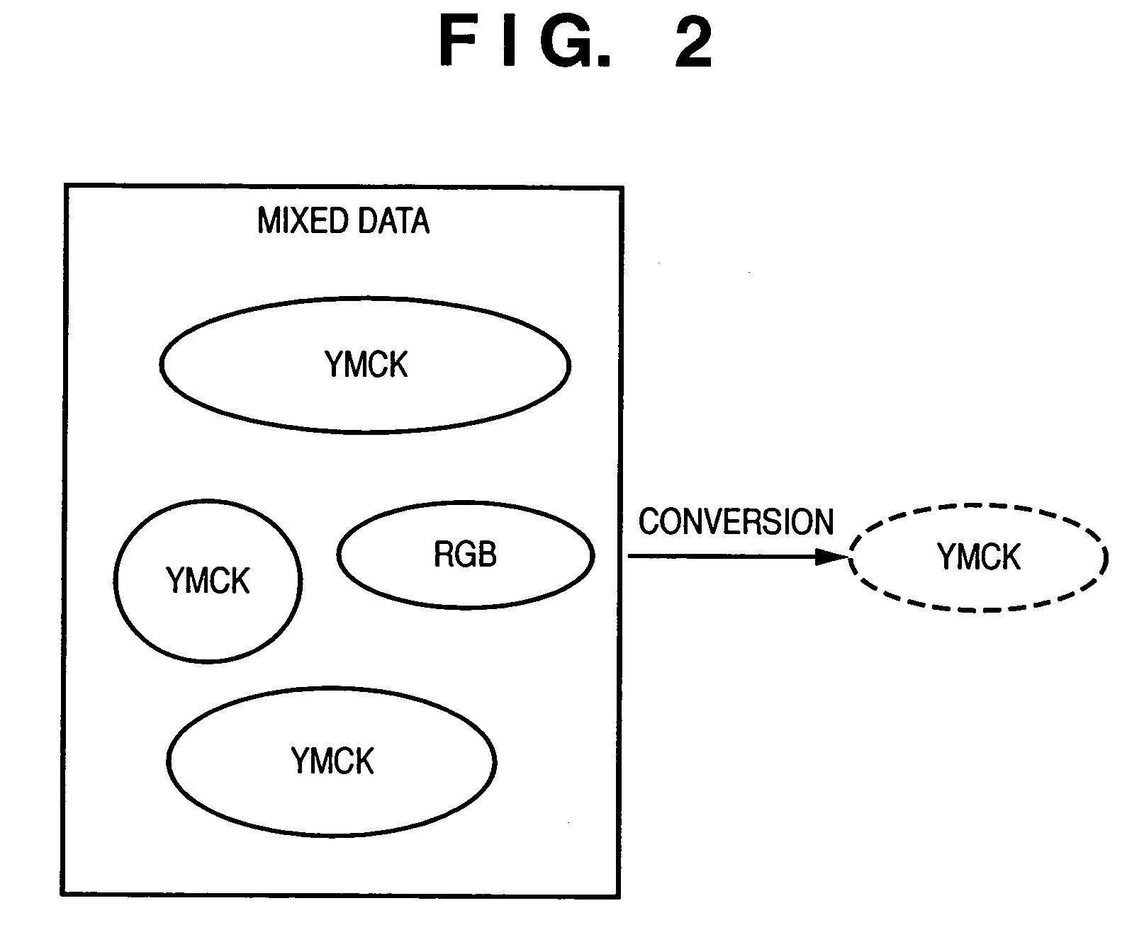
In a case where an image region to be processing in RGB color space and an image region to be processed in YMCK color space are mixed, if objects converted from RGB representation to YMCK representation are re-converted to RGB representation and RGB rendering is performed, the load on the system is increased, and the throughput of a printing apparatus is degraded. Accordingly, bands to be processed in the RGB color space are separated from print information inputted from a host computer, and pre-rendering is performed on the separated bands. Thereafter, bands to be processed in the YMCK color space are rendered by a rendering processing execution unit. The output order of the data of the respective bands pre-rendered in the RGB color space and that of the other bands are adjusted, and the data are sent to a printer engine.

Description

[0001]This is a continuation of PCT / JP03 / 03530, filed Mar. 24, 2003.TECHNICAL FIELD[0002]The present invention relates an image processing apparatus and its method and an image processing system and its control method, and more particularly, to image processing for performing rendering processing based on print information in accordance with a print request.BACKGROUND ART[0003]In a host computer, an application program such as a word processor or a spreadsheet operates on a basic software program such as Windows (trademark of Microsoft Corporation). In a case where printing is performed by using a printing apparatus, such application program calls a function of graphic subsystem among subsystems provided by the basic software program.[0004]For example, the graphic subsystem, which is called a “GDI” (Graphic Device Interface) in the Windows system, handles processing on image information for display and / or a printer. To absorb the difference in functions and characteristics of the re...

Claims


Application Information

Patent Timeline
Patent Type & Authority Patents(United States)
IPC IPC(8): H04N1/60B41J5/30B41J2/525G06F3/12H04N1/46
CPCH04N1/60
Inventor KURODA, YUJI
Owner CANON KK
Learn More