Disk reproducing device to prevent faulty operation in loading operation

a technology of a reproducing device and a loading operation, which is applied in the field of reproducing devices, can solve the problems of increasing the possibility of causing an operation stop, faulty operation, and increasing the load on other mechanisms, so as to ensure the reproducing operation and suppress the increase in manufacturing costs

Inactive Publication Date: 2006-05-02
MITSUBISHI ELECTRIC CORP
View PDF1 Cites 5 Cited by
  • Summary
  • Abstract
  • Description
  • Claims
  • Application Information

AI Technical Summary

Benefits of technology

[0014]This invention has been made to solve the problem described above, and the object of the present invention is to provide a disk reproducing device that can surely return a sliding member to an original position and prevent the occurrence of a faulty operation.
[0016]As described above, according to the present invention, the turning member is provided with a pushing portion for pushing the sliding member toward the original position when the turning member turns in response to an operation of transferring the ejected disk, so that it is possible to produce an effect of forcibly returning the sliding member to the original position. This can produce an effect of surely stabilizing operation of the disk reproducing device. Further, since the pushing portion is provided on the existing turning member, it is possible to produce an effect of suppressing an increase in manufacturing cost without increasing the number of parts and the number of assembling man-powers.

Problems solved by technology

However, the conventional disk reproducing device is constituted in a manner described above, so that it has the following problem.
In such case, there is happened a problem that a faulty operation will occur at the timing of an operation of loading the next disk.
In this respect, in order to stably attain a return of the first slider rack 11, there is also a method of simply setting spring load of the coil spring 13 at a higher value, but this higher spring load results in increasing a load to other mechanism and thus increasing a possibility of causing an operation stop, so that this method can not be adopted.

Method used


Image

  • Disk reproducing device to prevent faulty operation in loading operation
  • Disk reproducing device to prevent faulty operation in loading operation
  • Disk reproducing device to prevent faulty operation in loading operation

Examples


embodiment 1

Preferred Embodiment 1

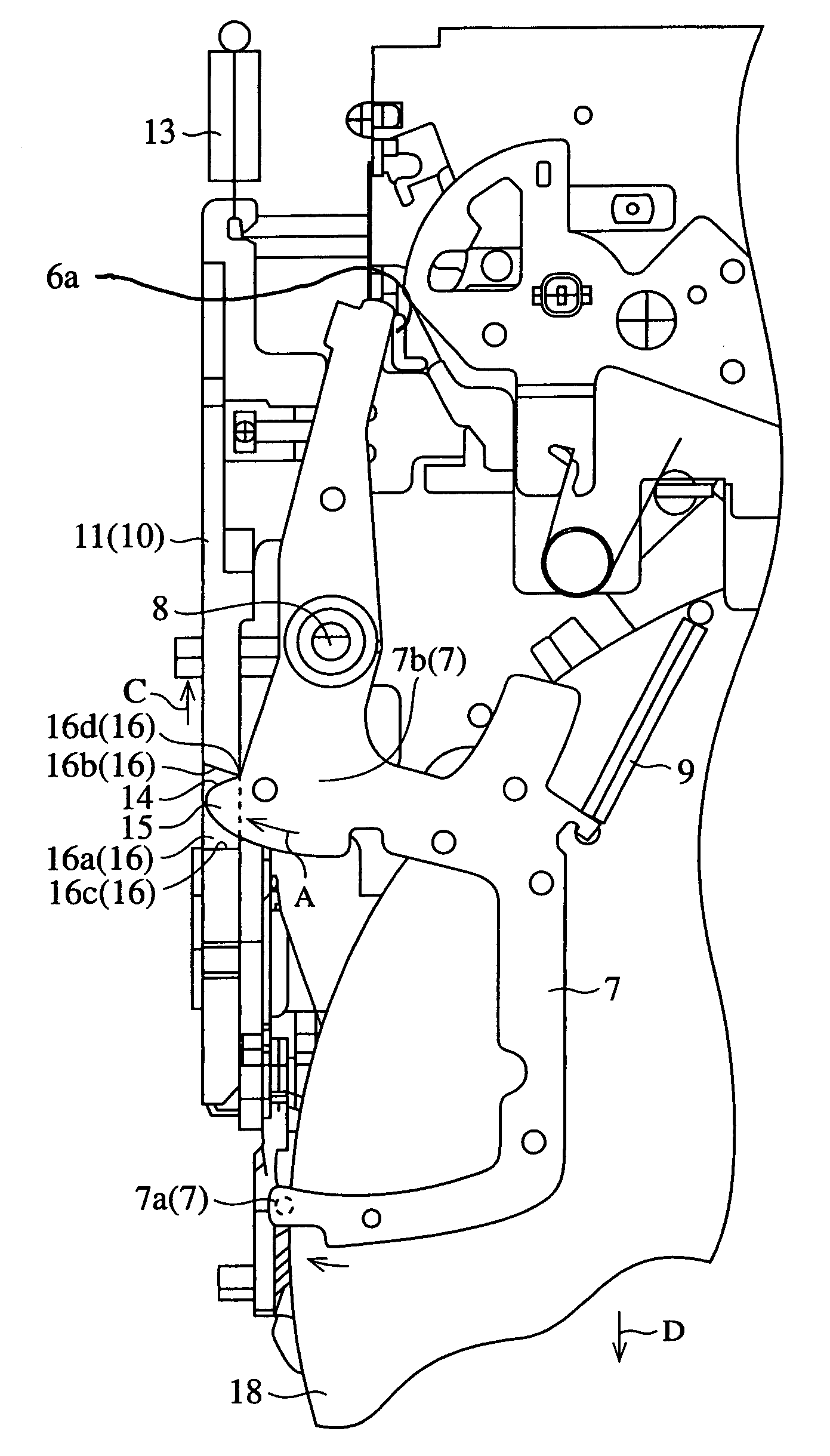
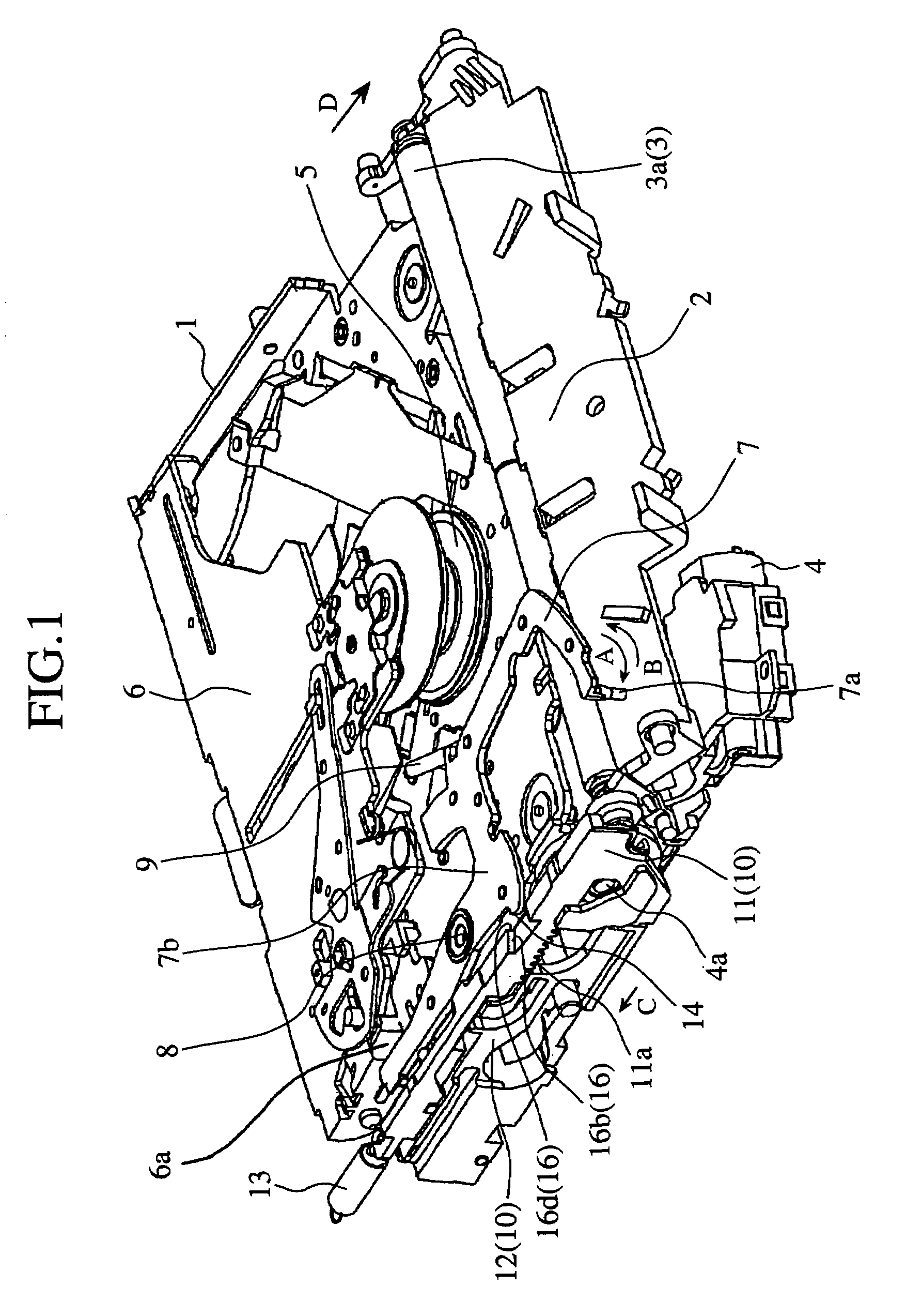
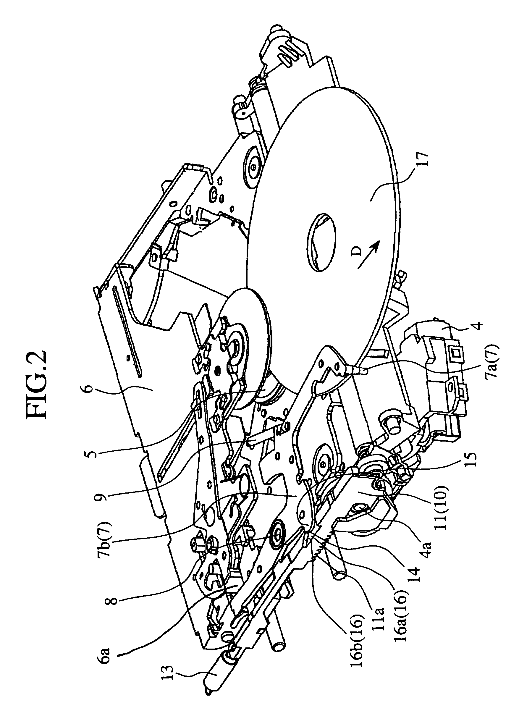
[0030]FIG. 1 is a schematic perspective view to show inside constitution of a disk reproducing device in accordance with embodiment 1 of the present invention, FIG. 2 is a schematic perspective view to show an operation of ejecting a small diameter disk in the disk reproducing device shown in FIG. 1 and FIG. 3 is a schematic perspective view to show an operation of ejecting a large diameter disk in the disk reproducing device shown in FIG. 1. FIG. 4 is a schematic enlarged plan view to show an operation of ejecting a large diameter disk in the disk reproducing device shown in FIG. 3, FIG. 5 is a schematic perspective view to show a state in which a large diameter disk is centered (clamped) in the disk reproducing device shown in FIG. 1 and FIG. 6 is a schematic perspective view to show a state in which a large diameter disk clamped and shown in FIG. 5 is reproduced. At this point in the constituent elements of this preferred embodiment 1, elements common to the...

embodiment 2

Preferred Embodiment 2

[0041]FIG. 7 is a schematic perspective view to show relevant part of the disk reproducing device in accordance with embodiment 2 of the present invention, and FIG. 8 is a schematic plan view to show relevant part of the disk reproducing device shown in FIG. 7. Here, of the constituent elements of this preferred embodiment 2, elements common to the constituent elements of the preferred embodiment 1 are denoted by the same reference symbols and their further descriptions will be omitted.

[0042]A feature of this preferred embodiment is different from that of the preferred embodiment 1 and it lies in that the rear wall surface 16b is formed such that a distance between the rear wall surface 16b and the front wall surface 16c gradually increases inward in a direction of thickness of the first slider rack 11, as shown in FIG. 7 and FIG. 8.

[0043]In this preferred embodiment 2, when the disk size selecting lever 7 turns in a direction shown by an arrow A at the time wh...

embodiment 3

Preferred Embodiment 3

[0045]FIG. 9 is a schematic perspective view to show inside constitution of a disk reproducing device in accordance with embodiment 3 of the present invention, and FIG. 10 is a schematic plan view to show relevant part of the disk reproducing device shown in FIG. 9. Here, of the constituent elements of this preferred embodiment 2, elements common to the constituent elements of the preferred embodiment 1 are denoted by the same reference symbols and their further descriptions will be omitted.

[0046]A feature of this preferred embodiment is different from those of the preferred embodiment 1 and the preferred embodiment 2 and it lies in that, in replace of the through groove 16, a concave portion 19 is provided at a position in upper portion of the first slider rack 11 where the disk size selecting lever 7 is to abut against the first slider rack 11 and that corner portion of bending portion 7b of the disk size selecting lever 7 makes a pushing portion 20. The conc...


PUM

PropertyMeasurementUnit
diameteraaaaaaaaaa
diameteraaaaaaaaaa
diameteraaaaaaaaaa

Abstract

When a disk size selecting lever turns in a direction shown by an arrow A with an operation of ejecting a disk, its pushing surface pushes corner portion of a first slider rack in a state where it can not move, toward a direction shown by an arrow C. When the disk is completely ejected, the disk size selecting lever is returned in a direction shown by an arrow B by urging force of a coil spring and at the same time the first slider rack is forcibly returned to an original position by urging force of a coil spring.

Description

BACKGROUND OF THE INVENTION[0001]1. Field of the Invention[0002]The present invention relates to a disk reproducing device for reproducing information recorded on an optical disk such as a compact disk, a laser disk and the like.[0003]2. Description of the Related Art[0004]FIG. 11 is a schematic perspective view to show outside constitution of a conventional disk reproducing device and FIG. 12 is a schematic perspective view to show inside constitution of the conventional disk reproducing device shown in FIG. 11. Here, in the drawing, it is assumed that a lower right side is a front side and an upper left side is a rear side. In this respect, it is assumed that this relationship is common to the following respective perspective views.[0005]In the drawings, a reference numeral 1 denotes a chassis to constitute box of a disk reproducing device, 2 denotes a disk inserting opening which is made in front side of the chassis 1 and through which a small-diameter disk such as 8 cm disk or a...

Claims


Application Information

Patent Timeline
Patent Type & Authority Patents(United States)
IPC IPC(8): G11B17/04G11B17/051
CPCG11B17/051G11B17/0404
Inventor KOBAYASHI, MASAKISONODA, YOSHINORI
Owner MITSUBISHI ELECTRIC CORP
Why Eureka
Try Eureka