
Pressing iron having a handle integrating an orifice for filling a reservoir

a technology of reservoir and orifice, which is applied in the field of pressing iron furnished with a reservoir, can solve the problems of complicating the operation of filling the reservoir, and reducing the diameter of the orifice, so as to eliminate the drawbacks and achieve the effect of large diameter

Inactive Publication Date: 2006-05-09
SEB SA
View PDF7 Cites 4 Cited by
  • Summary
  • Abstract
  • Description
  • Claims
  • Application Information

AI Technical Summary

Benefits of technology

[0003]A goal of the invention is to eliminate these drawbacks by providing a pressing iron having a handle of a particular form permitting integration of a filling orifice that has a large diameter and is easily accessible.
[0005]Such a characteristic presents the advantage of permitting the attainment of a pressing iron having a relatively voluminous handle on which the palm of the hand can rest in a relaxed position during ironing and in which can be disposed a filling orifice that is easily accessible and of large diameter.
[0007]Such a characteristic permits the ease of filling of the reservoir to be increased.
[0010]Such a characteristic presents the advantage of permitting a perfect integration of the filling orifice into the body of the handle while retaining a smooth upper surface to support the palm of the hand.
[0013]Such a characteristic permits the utilization of a control dial of large diameter, the angular displacement of which can be effectuated very precisely by the user, thus permitting a very precise regulation of the organ controlled by the control dial.

Problems solved by technology

However, the filling orifice then presents the drawback of having a reduced diameter, because of the thinness of the iron at this location, which complicates the operation of filling the reservoir.

Method used


Image

  • Pressing iron having a handle integrating an orifice for filling a reservoir
  • Pressing iron having a handle integrating an orifice for filling a reservoir
  • Pressing iron having a handle integrating an orifice for filling a reservoir

Examples


Embodiment Construction

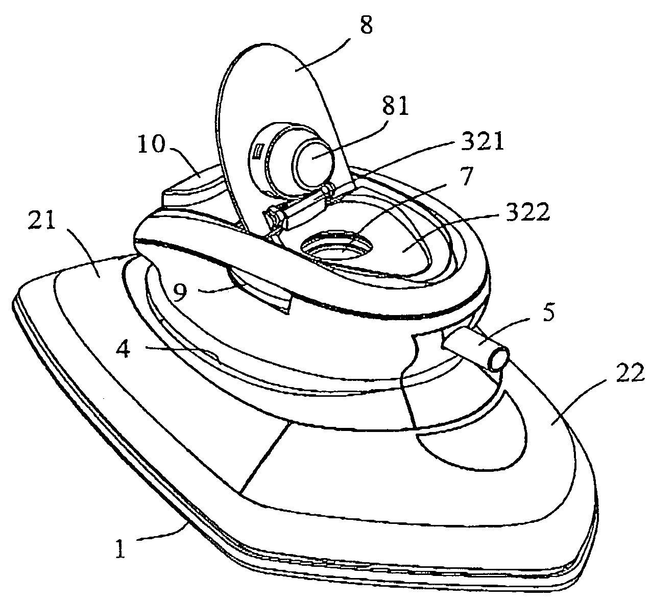
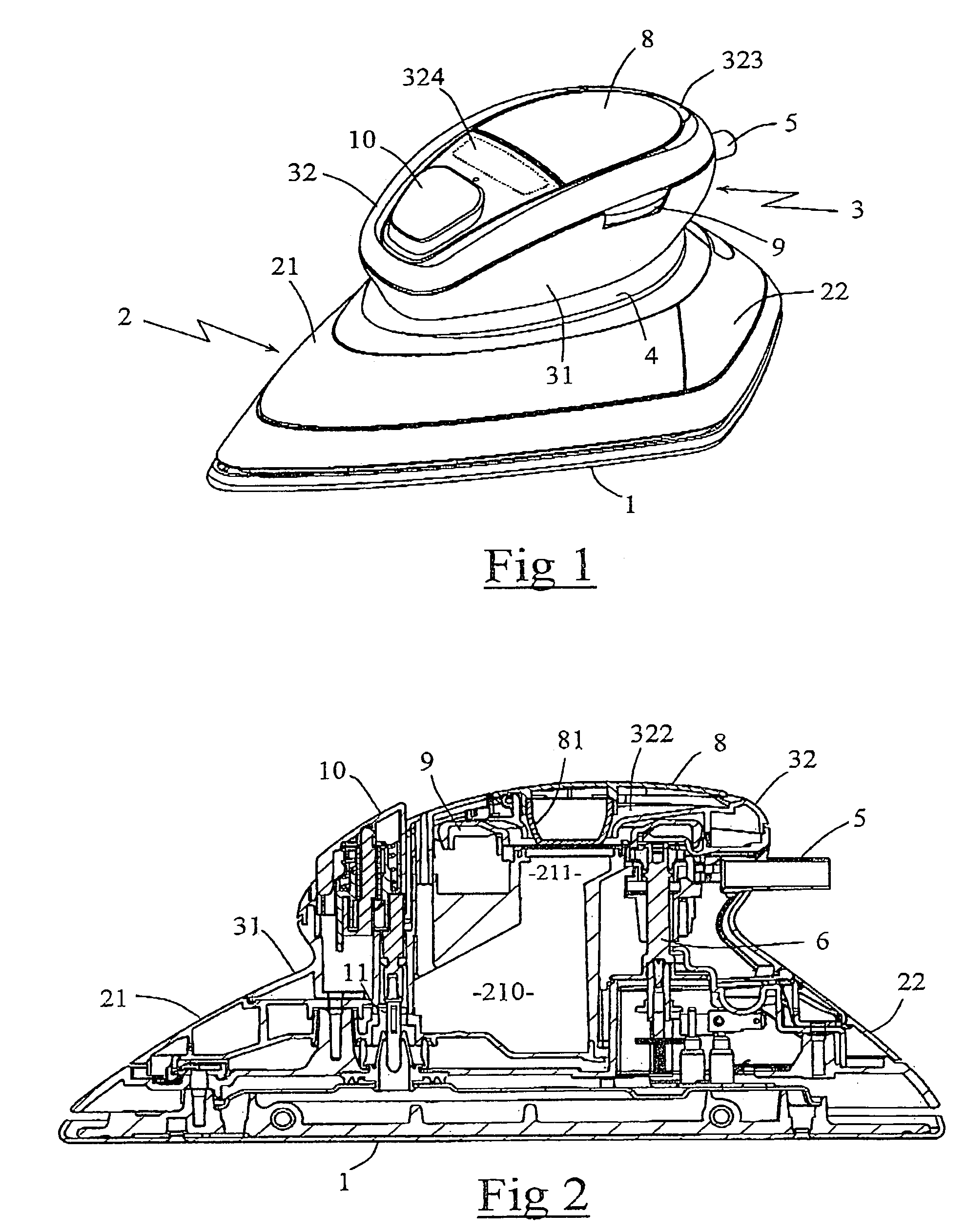
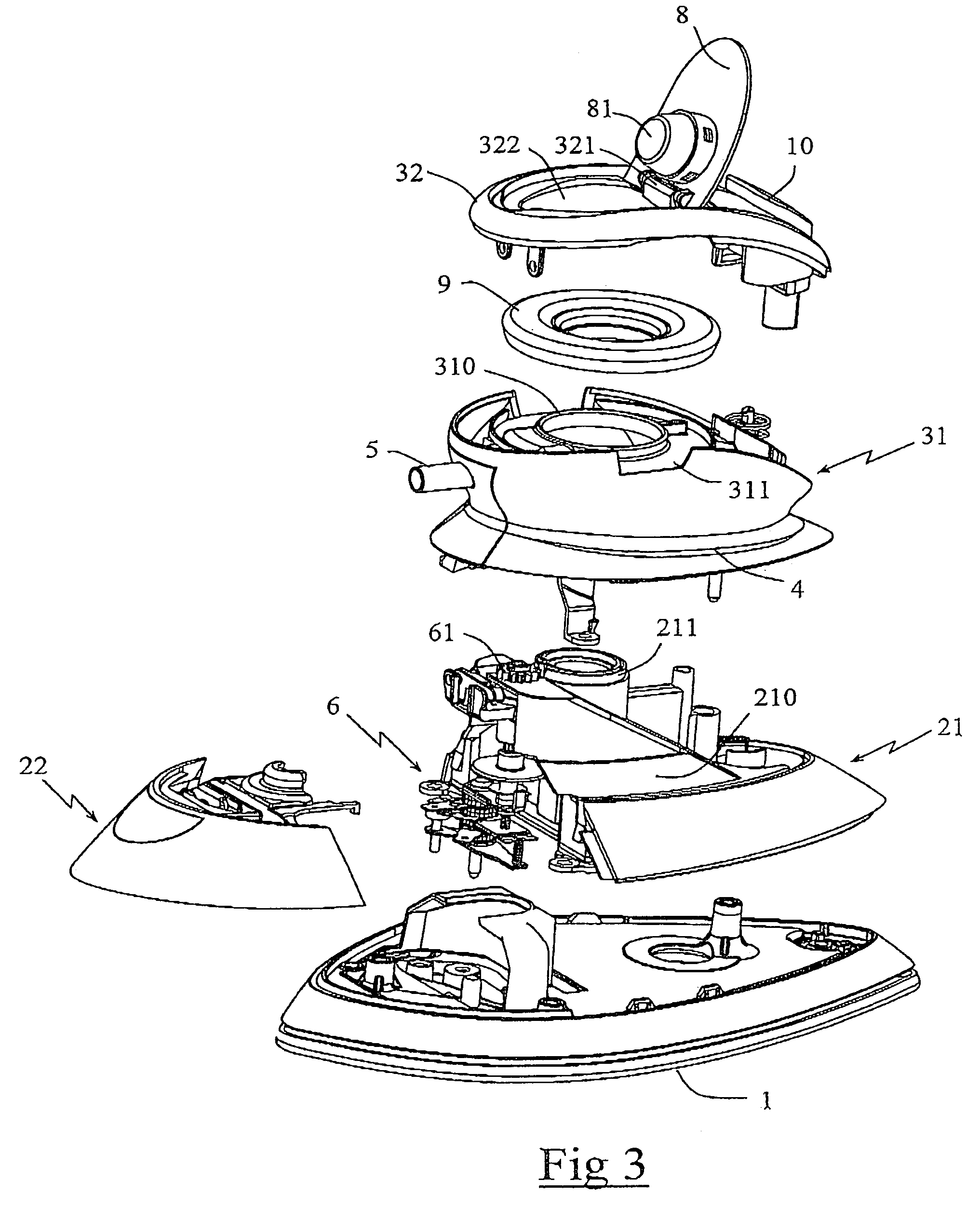
[0025]FIGS. 1 to 4 represent a steam pressing iron having a heating soleplate 1, topped by a body 2 presenting the form of a dome whose base is adjusted to the contour of soleplate 1 and the top of which presents a flared part supporting a handle 3 disposed substantially above the center of soleplate 1, handle 3 forming a protuberance on body 2 of the iron.

[0026]Handle 3 has a generally one-piece form, similar to a smooth, rounded stone, usually in the form of a parallelepiped having rounded edges, and has a convex upper surface that is slightly inclined toward the front of the iron, conforming to the natural curvature of the palm and fingers of the hand when this latter is in a relaxed but slightly closed position.

[0027]The width of handle 3 at the level of its base is less than the width of the widened top of body 2 of the iron such that there results at one side and the other of the handle a rim, or edge, 4. This rim 4 serves as an abutment for the fingers of the hand when the pa...


PUM


Abstract

A pressing iron having a heating soleplate topped by a body and a handle forming a protuberance on the body of the iron, the body enclosing a reservoir. The handle presents an upper surface forming a bearing surface for the palm of the hand presenting, at least locally, a width greater than or equal to 4 cm and lateral walls extending from the upper surface of the handle to the body of the iron intended to receive the fingertips and the handle integrates a filling orifice for the reservoir opening at a surface of the handle.

Description

BACKGROUND OF THE INVENTION[0001]The present invention relates to a pressing iron furnished with a reservoir having a filling orifice and more particularly to a pressing iron in which the handle forms a protuberance on the body of the iron.[0002]Most steam irons have an elongated handle of cylindrical form extending along the longitudinal axis of the iron and permitting grasping of the iron by taking hold of it with a “hammer” grip of the handle. Such steam irons are generally provided with a reservoir whose filling orifice is disposed on the front part of the iron ahead of the handle. However, the filling orifice then presents the drawback of having a reduced diameter, because of the thinness of the iron at this location, which complicates the operation of filling the reservoir.BRIEF SUMMARY OF THE INVENTION[0003]A goal of the invention is to eliminate these drawbacks by providing a pressing iron having a handle of a particular form permitting integration of a filling orifice that ...

Claims


Application Information

Patent Timeline
Patent Type & Authority Patents(United States)
IPC IPC(8): D06F75/14D06F75/30D06F75/34
CPCD06F75/14D06F75/34D06F75/265
Inventor RENAULT, FABRICEGELUS, DOMINIQUEHIPP, EDGAR
Owner SEB SA
Learn More