Pneumatic tire

a pneumatic tire and pneumatic technology, applied in the field of pneumatic tires, can solve the problems of increased weight, increased weight, increased weight, etc., and achieve the effect of increasing workability and minimizing the increase in weigh

Inactive Publication Date: 2006-05-09
HONDA MOTOR CO LTD +1
View PDF8 Cites 8 Cited by
  • Summary
  • Abstract
  • Description
  • Claims
  • Application Information

AI Technical Summary

Benefits of technology

[0009]The purpose of the present invention is to provide a pneumatic tire, comprising an adhesive sealant applied onto the inner surface thereof, whereby an increase in the weight can be minimized and workability in handling the tire can be increased.
[0011]As described above, by disposing the air barrier membrane stacked with the adhesive sealant on the inner surface of the tire with intervening the air part, when a nail or the like sticks in the tire, the air is exhausted to the inside of the tire from the space part at a position where the nail or the like is stuck. At the same time, the air barrier membrane at the stuck position adheres to the inner surface of the tire through the adhesive sealant. Thus, the air filled in the tire is prevented from leaking.
[0012]Thus, since the main sealing function is performed by the air barrier membrane and the adhesive sealant functions as an adhesive agent, the adhesive sealant to be used is reduced in quantity, and the tire can be prevented from being increased in weight.

Problems solved by technology

However, the method (1) of using the run-flat tire has the problems that it is increased in weight due to the rigid material, and riding comfort is also damaged.
However, there is the other problem that the driver must come out of the car for performing the injection work when the tire gets punctured.
However, although the method (3) is more advantageous than the methods (1) and (2), the adhesive sealant needs to be disposed on the inner surface of the tire to a certain extent in thickness, therefore, the increase in weight cannot be avoided compared with a normal tire, and this results in increasing a fuel consumption of a car.
Moreover, since the adhesive sealant is exposed on the inner surface of the tire in the method (3), the workability is bad because the adhesive sealant sticks to the hands or the like when mounting or dismounting the tire on / from a vehicle.

Method used


Image

  • Pneumatic tire
  • Pneumatic tire
  • Pneumatic tire

Examples


Embodiment Construction

[0017]The preferred embodiment of the present invention shown in the attached drawings will be explained in details below.

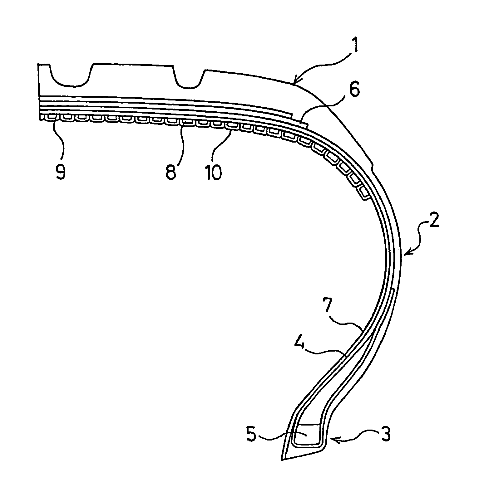
[0018]FIG. 1 illustrates an example of the pneumatic tire in accordance with the present invention, and shows a meridian half sectional view. In FIG. 1, the reference 1 is a tread part; the reference 2 is a side wall part; and the reference 3 is a bead part. A carcass layer 4 is mounted between a pair of right and left bead parts 3, 3, and both of their end parts in the width direction of the tire are turned up around the respective bead cores from the inside to the outside of the tire. A belt layer 6 is mounted on the outer circumferential side of the carcass layer 4 in the tread part 1, and an inner liner 7 is arranged inside of the carcass layer 4.

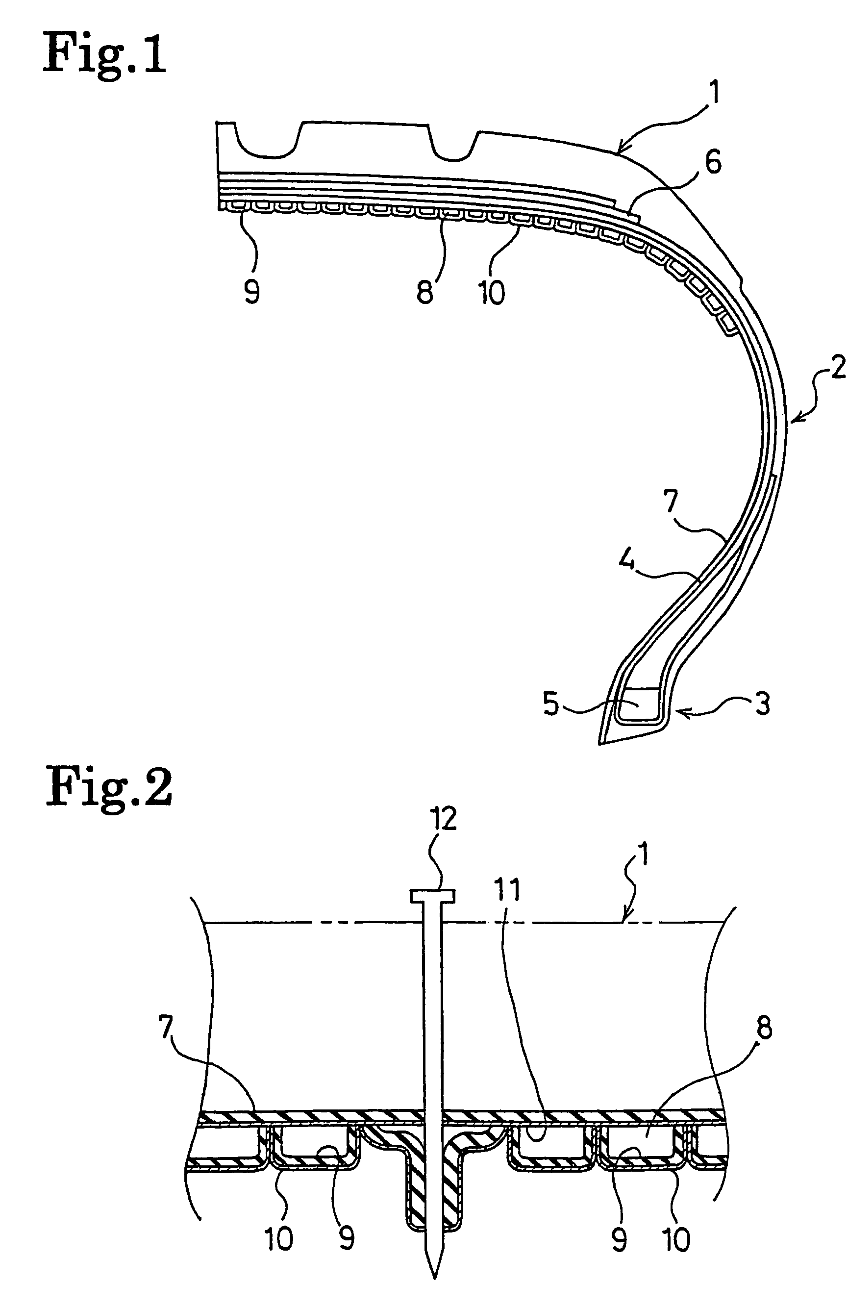
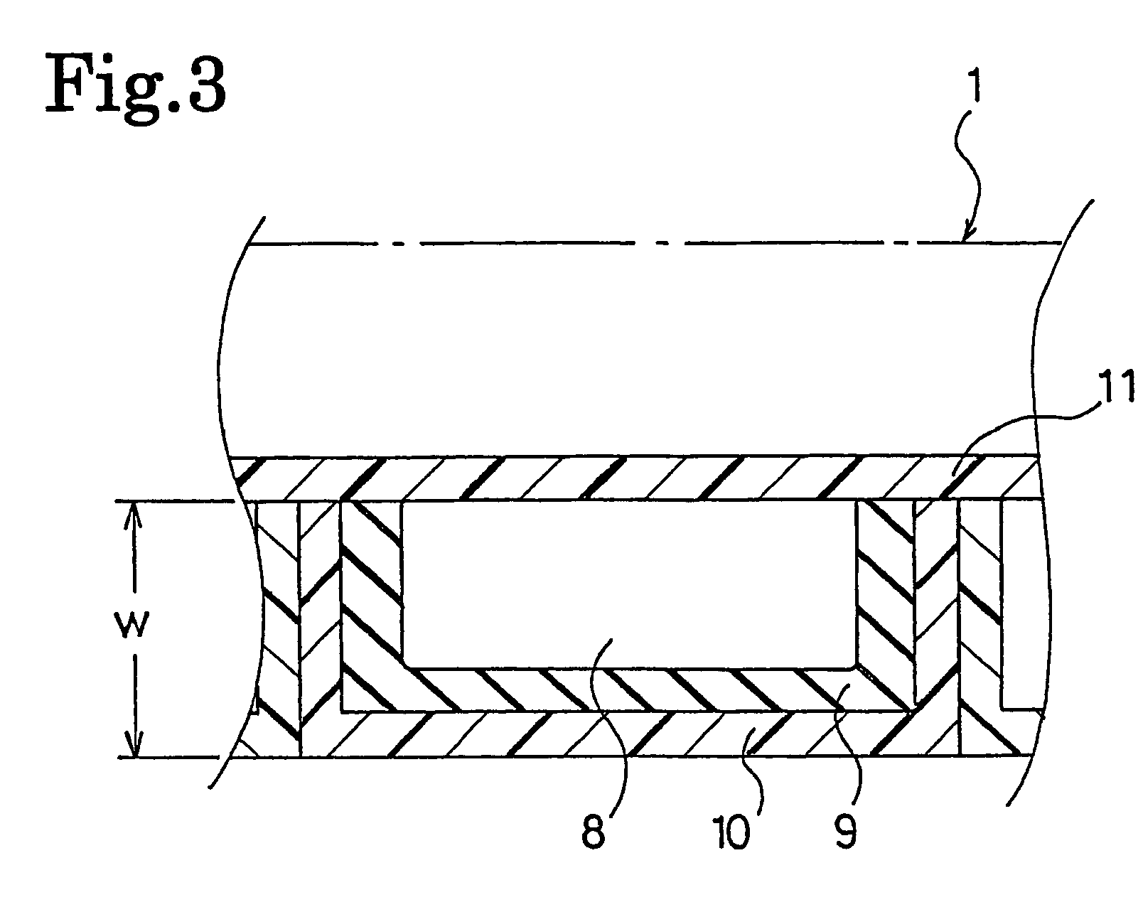
[0019]In the position on the inner surface of the inner liner 7 corresponding to the tread part 1, an air barrier membrane 10 forming a plurality of independent air rooms is disposed along the inner surface of the ti...


PUM

PropertyMeasurementUnit
thicknessaaaaaaaaaa
thicknessaaaaaaaaaa
thicknessaaaaaaaaaa

Abstract

A pneumatic tire, comprising adhesive sealant applied onto the inner surface thereof, wherein an air barrier membrane is disposed on the inner surface of the tire at least at a tread part, a space part is formed between the air barrier membrane and the inner surface of the tire, and the adhesive sealant is stacked on the space part side surface of the air barrier membrane, whereby an increase in weight can be minimized and a workability in handling the tire can be increased.

Description

BACKGROUND OF THE INVENTION[0001]1. Field of the Invention[0002]The present invention relates to a pneumatic tire comprising a self-sealing function, to be more specific, a pneumatic tire provided with an adhesive sealant on the inner surface of the tire.[0003]2. Detailed Description of the Prior Art[0004]Conventionally, as measures against a flat tire when a car treads on a nail or the like during running, the following methods have been proposed, such as (1) use of a run-flat tire in which a rigid member is pre-inserted, (2) stopping up the hole by injecting a liquid repair agent into the tire from an air valve when getting a flat tire, (3) pre-lamination of an adhesive sealant on the inner surface of the tire at the time of manufacturing it.[0005]However, the method (1) of using the run-flat tire has the problems that it is increased in weight due to the rigid material, and riding comfort is also damaged. The method (2) of injecting a repair liquid has a less problem about the in...

Claims


Application Information

Patent Timeline
Patent Type & Authority Patents(United States)
IPC IPC(8): B60C19/12B29C73/20B29C73/22B60C5/12B60C5/14B60C5/20
CPCB29C73/20B29C73/22B29D30/0685B60C5/142B60C5/20B60C19/12B60C5/12B29D2030/0689B29D2030/0695B29L2030/00Y10T152/10522Y10T152/10684Y10T152/10693
Inventor NAKAKITA, ISSEINAITO, MITSURUFUKUTOMI, TAKASHI
Owner HONDA MOTOR CO LTD
Why Eureka
Try Eureka