
Electromagnetic clutch-controlled electric blind

Inactive Publication Date: 2006-05-09
IND TECH RES INST +1
View PDF9 Cites 16 Cited by
  • Summary
  • Abstract
  • Description
  • Claims
  • Application Information

AI Technical Summary

Benefits of technology

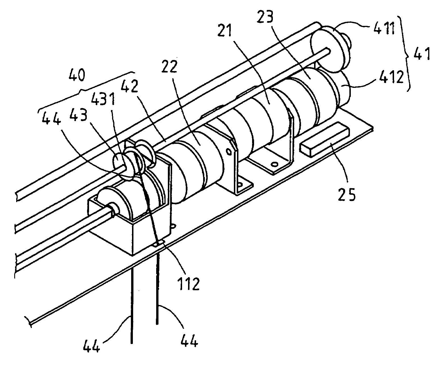
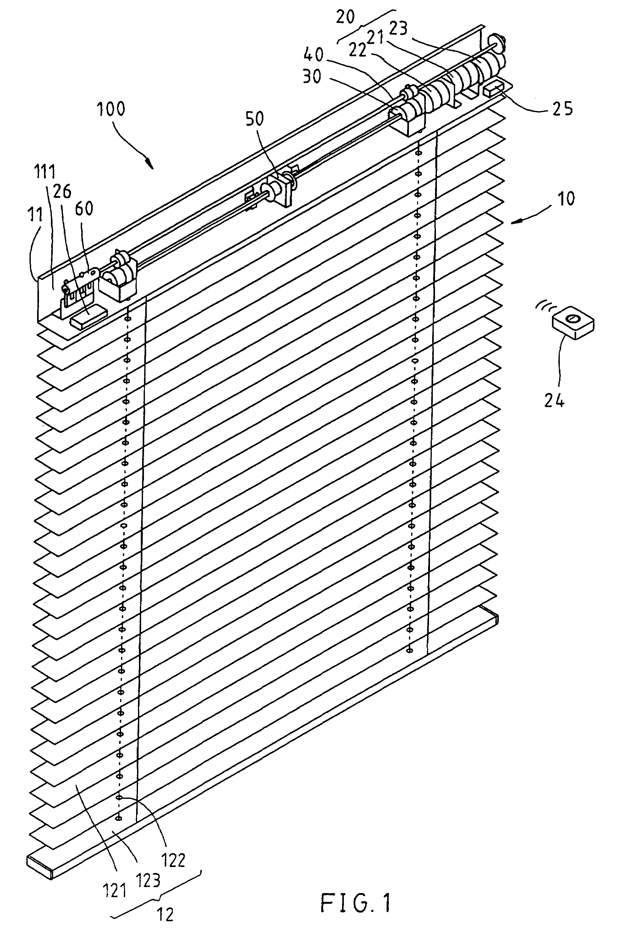
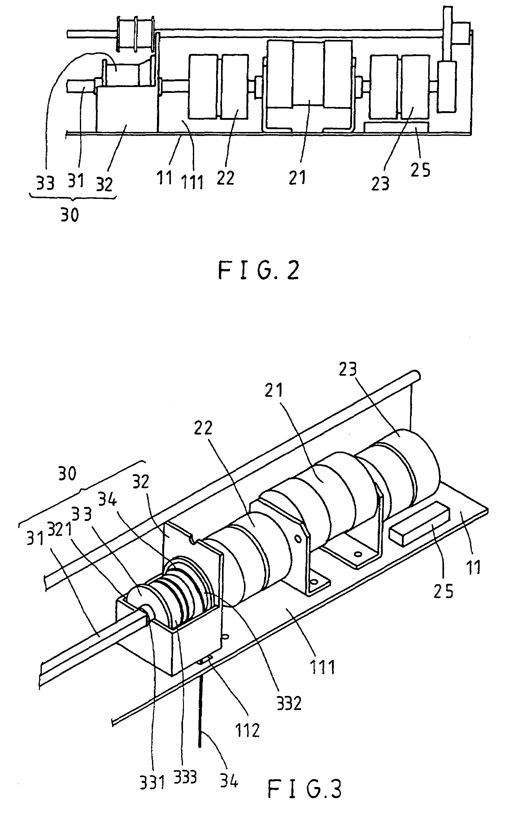
[0007]The present invention has been accomplished to provide an electromagnetic clutch-controlled electric blind, which eliminates the aforesaid drawbacks. It is the main object of the present invention to provide an electromagnetic clutch-controlled electric blind, which controls lifting / lowering of the slats and bottom rail of the Venetian blind as well as tilting of the slats. It is another object of the present invention to provide an electromagnetic clutch-controlled electric blind, which is compact, and requires less installation space. It is still another object of the present invention to provide an electromagnetic clutch-controlled electric blind, which is inexpensive to manufacture. To achieve these objects of the present invention, the electromagnetic clutch-controlled electric blind comprises a blind body formed of a headrail, a set of slats, and a bottom rail, a power drive, the power drive including a reversible motor and electromagnetic clutch means connectable to the motor, an amplitude modulation set coupled to the motor for rotation with the motor to lift / lower the slats to the desired elevation, a frequency modulation set coupled to the motor through the electromagnetic clutch means and adapted for controlling tilting angle of the slats.

Problems solved by technology

When adjusting the elevation of the bottom rail, the user must approach the blind and pull the lift cord by hand with much effort.
Further, because the lift cord is not kept out of reach of children, children may pull the lift cord for fun.
In case the lift cord is hung on a child's head, a fetal accident may occur.
This operation manner is still not convenient.

Method used


Image

  • Electromagnetic clutch-controlled electric blind
  • Electromagnetic clutch-controlled electric blind
  • Electromagnetic clutch-controlled electric blind

Examples


second embodiment

[0033]FIG. 11 is a system block diagram showing the present invention. According to this embodiment, the amplitude modulation set 30 is directly coupled to the motor 21, and the frequency modulation set 40 is coupled to the motor 21 through the transmission gear set 41 and the electromagnetic clutch 23. When lifting / lowering the slats, switch off the electromagnetic clutch 23 to disconnect the frequency modulation set 40 from the motor 21. When tilting the slats, switch on the electromagnetic clutch 23 to connect the frequency modulation set 40 to the motor 21. At this time, the amplitude modulation set 30 moves slightly following the action of the frequency modulation set 40. However, because this movement causes the bottom rail to be lifted or lowered within a short distance only, this insignificant amount of movement does not affect the reliability of the operation.

third embodiment

[0034]FIG. 12 is a system block diagram showing the present invention. According to this embodiment, the motor 21′ is a single side motor coupled to the transmission gear set 41; the amplitude modulation set 30 and the frequency modulation set 40 are connected in parallel to the transmission gear set 41 through the electromagnetic clutches 22;23 respectively.

fourth embodiment

[0035]FIG. 13 is a system block diagram showing the present invention. According to this embodiment, the motor 21′ is a single side motor coupled to the transmission gear set 41; the amplitude modulation set 30 is directly connected to the transmission gear set 41; the frequency modulation set 40 is connected to the transmission gear set 41 through the electromagnetic clutch 23.


PUM


Abstract

An electromagnetic clutch-controlled electric blind is constructed to include a blind body formed of a headrail defining a receiving chamber, a set of slats, and a bottom rail, a power drive, the power drive including a reversible motor and electromagnetic clutch apparatus connectable to the motor, an amplitude modulation set coupled to the motor for rotation with the motor to lift / lower the slats to the desired elevation, a frequency modulation set coupled to the motor through the electromagnetic clutch apparatus and adapted for controlling tilting angle of the slats.

Description

[0001]This is a continuation of parent application Ser. No. 10 / 143,770 filed May 14, 2002 now U.S. Pat. No. 6,789,597.BACKGROUND OF THE INVENTION[0002]1. Field of the Invention[0003]The present invention relates to Venetian blinds and, more specifically, to an electromagnetic clutch-controlled electric blind.[0004]2. Description of the Related Art[0005]A regular Venetian blind comprises headrail, a bottom rail, a plurality of slats arranged in parallel between the headrail and the bottom rail, an amplitude modulation control mechanism for controlling lifting and positioning of the bottom rail to change the extending area of the blind, a frequency modulation control mechanism for controlling the tilting angle of the slats to regulate the light. The amplitude modulation control mechanism comprises an endless lift cord suspended from the headrail at one lateral side for pulling by hand to lift / lower the bottom rail. The frequency modulation control mechanism comprises a frequency modul...

Claims


Application Information

Patent Timeline
IPC IPC(8): E06B9/30E06B9/304E06B9/32E06B9/322
CPCE06B9/304E06B9/322Y10S160/17E06B2009/3225
Inventor WEN, YU-CHELUI, SONG-HEHSU, YA-WEI
Owner IND TECH RES INST
Learn More