Soap dispensing apparatus

a technology for dispensing apparatuses and soaps, which is applied in the direction of brushes, hand devices, applications, etc., can solve the problems of relative complexity or high manufacturing cost, and achieve the effect of adding structural and operating advantages

Active Publication Date: 2006-05-09
HELEN OF TROY LIMITED
View PDF49 Cites 69 Cited by
  • Summary
  • Abstract
  • Description
  • Claims
  • Application Information

AI Technical Summary

Benefits of technology

[0003]It is a general object of the invention to provide an improved fluid-dispensing implement which avoids the disadvantages of prior such implements while affording additional structural and operating advantages.
[0007]Still another feature of the invention is the provision of an implement of the type set forth, which is of relatively simple and economical construction.

Problems solved by technology

However, such prior apparatuses have typically been characterized by either a relatively complex or expensive-to-manufacture construction or have valve actuating mechanisms which are inefficient.

Method used


Image

  • Soap dispensing apparatus
  • Soap dispensing apparatus
  • Soap dispensing apparatus

Examples


Embodiment Construction

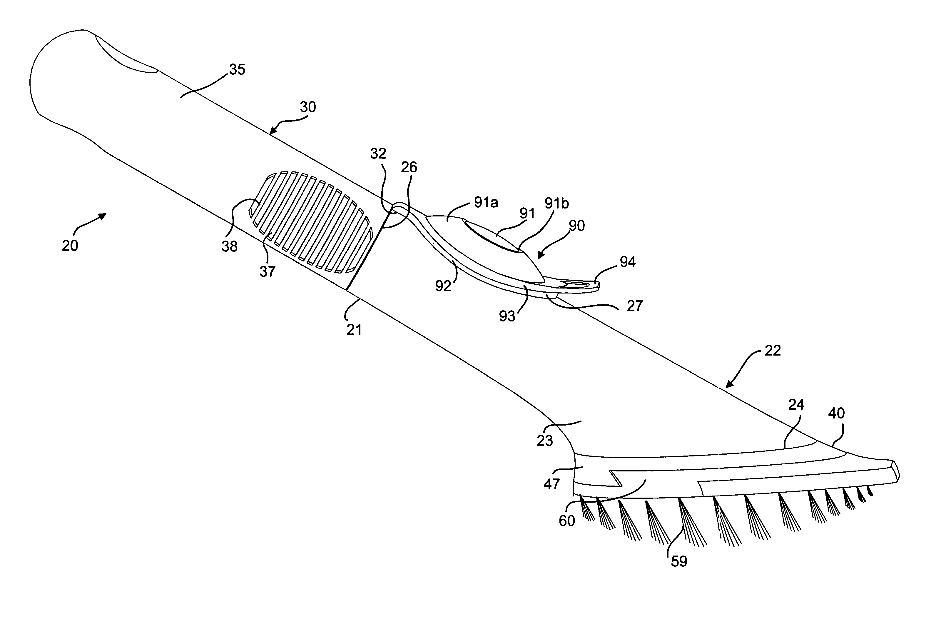
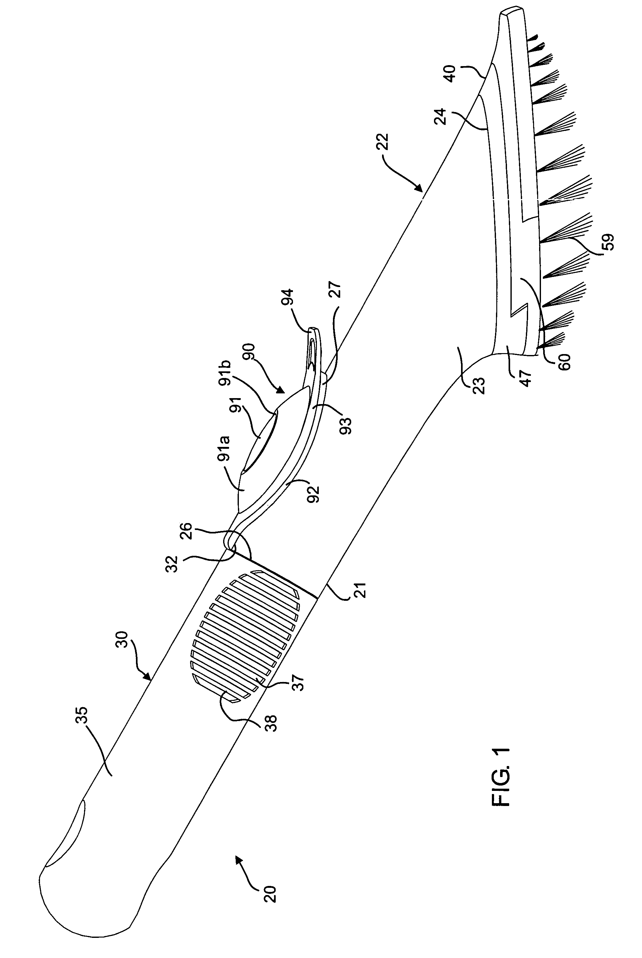
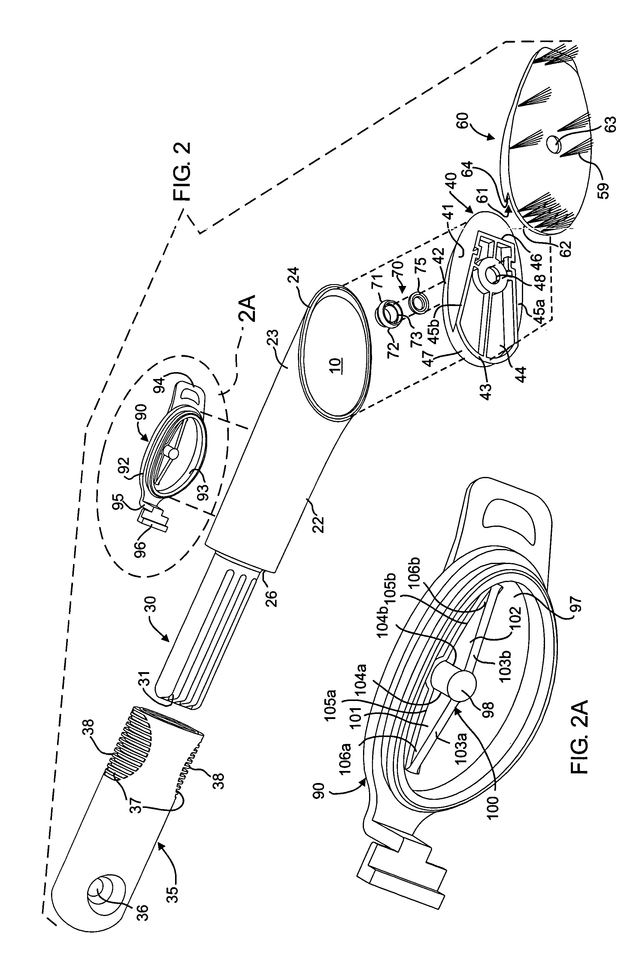
[0020]Referring to FIGS. 1 and 2, there is illustrated a fluid-dispensing implement in the nature of a kitchen apparatus 20, constructed in accordance with and embodying the features of the present invention. The apparatus 20 has a handle or housing 21, which includes a body 22 with a hollow, tubular front portion 23 closed by an end plate 40, for cooperation therewith to define a fluid reservoir 10. The hollow tubular front portion 23 flares outwardly, forwardly terminating in a front end 24. In an embodiment, a flange 25 may be provided which can be used as a scraper or the like (See FIGS. 4 and 5). Opposite the tubular front portion 23 is an end wall 26 that is provided at its upper side with an oval aperture 27, adjacent to the end wall 26 for receiving a button 90 (described in detail below). The oval aperture 27 and body 22 is constructed according to that disclosed in U.S. Pat. No. 6,250,833 incorporated herein by reference.

[0021]Integral with the end wall 26 and projecting r...


PUM


Abstract

A fluid-dispensing kitchen apparatus has a body including a fluid reservoir and a handle, the reservoir being closed by an end plate which is welded to the body and is, in turn, latched to a cleaning medium block. An embodiment has a resilient tab on the block engaging an edge of the housing plate. Aligned holes through the plate and the block which provide communication between the reservoir and the plate is openable and closeable by a valve actuated by an increase in pressure provided by depressing a resilient button. In an embodiment, the resilient button includes a bias member to return the button to its rest position.

Description

[0001]The present invention relates to fluid-dispensing implements or utensils, and in particular to household cleaning implements or utensils, such as brushes or sponges and the like. The invention has particular application to a kitchen apparatus or wand which is capable of dispensing liquid soap or detergent.BACKGROUND OF THE INVENTION[0002]Many fluid-dispensing apparatuses have heretofore been provided. Such apparatuses typically include a fluid reservoir, a closeable opening for filling the reservoir, and a manually actuated valve mechanism for dispensing fluid from the reservoir to the area of the apparatus bristles or sponge. However, such prior apparatuses have typically been characterized by either a relatively complex or expensive-to-manufacture construction or have valve actuating mechanisms which are inefficient.SUMMARY OF THE INVENTION[0003]It is a general object of the invention to provide an improved fluid-dispensing implement which avoids the disadvantages of prior s...

Claims


Application Information

Patent Timeline
Patent Type & Authority Patents(United States)
IPC IPC(8): A46B11/00A46B11/02A46B11/04B43K5/00A46B5/02A47KA47L13/22A47L17/04B43K8/12
CPCA46B11/0013A47L17/04A46B2200/3033A46B11/0041
Inventor KLIEGMAN, ADRIANADRUMMOND, ALEC HOLLYDIBDIN, STEVENLOOR, WILFRIDOJERSTROEM, GOERANJACOBSEN, JOHN THOMAS
Owner HELEN OF TROY LIMITED
Why Eureka
Try Eureka