Gear pump with gears having curved teeth and method of feeding elastomeric material

a gear pump and gear technology, applied in the direction of machines/engines, liquid fuel engines, positive displacement liquid engines, etc., can solve the problems of uneven extrusion of components, non-compliance with building tire specifications, and non-uniform extrusion of components, and achieve the effect of smooth material squeez

Inactive Publication Date: 2006-05-09
THE GOODYEAR TIRE & RUBBER CO
View PDF19 Cites 22 Cited by
  • Summary
  • Abstract
  • Description
  • Claims
  • Application Information

AI Technical Summary

Benefits of technology

[0009]In order for the elastomeric material to be squeezed without being damaged by excessive pressure the herringbone gears are provided with curved central portions which have a circumferential width equal to at least one half the pitch of the gear teeth. Accordingly, when the gear teeth of the opposing gears come together there is a gradual closing of the space between the gear teeth for diverting the pumped material towards the outlet chamber in the gear pump housing. In this way there is a gradual unloading of the material between the gear teeth as the gears rotate past the outlet chamber in the gear pump housing. Also, the pinching or pulsating flow of the material is minimized significantly.
[0012]In accordance with a further aspect of the invention there is provided a method of pumping elastomeric material through a gear pump having an inlet chamber, an outlet chamber and a metering chamber, a pair of gears having herringbone gear teeth disposed in said metering chamber at a predetermined pitch, each of the teeth having helical side portions and a curved central portion comprising feeding the material under pressure into the inlet chamber, rotating the gears to convey the material through the metering chamber into the outlet chamber and smoothly squeezing the material out of the space between the meshing gear teeth at the curved central portion and then over the gear teeth into the outlet chamber as the gear teeth seal the space between the outlet chamber and the inlet chamber.

Problems solved by technology

This results in extruded components which are not uniform and do not meet the specifications for building tires.
This temperature differential is not desirable because the viscosity of the rubber will then be greater on one side resulting in a non-uniform extrusion of the component.
However, there is no teaching or showing of utilizing curved gear teeth in a gear pump.
The teeth are joined at sharp central edges which cause high pressure spikes resulting in an increase in temperature of the elastomeric material at the central portions of the component which may produce a non-uniform component.

Method used


Image

  • Gear pump with gears having curved teeth and method of feeding elastomeric material
  • Gear pump with gears having curved teeth and method of feeding elastomeric material
  • Gear pump with gears having curved teeth and method of feeding elastomeric material

Examples


Embodiment Construction

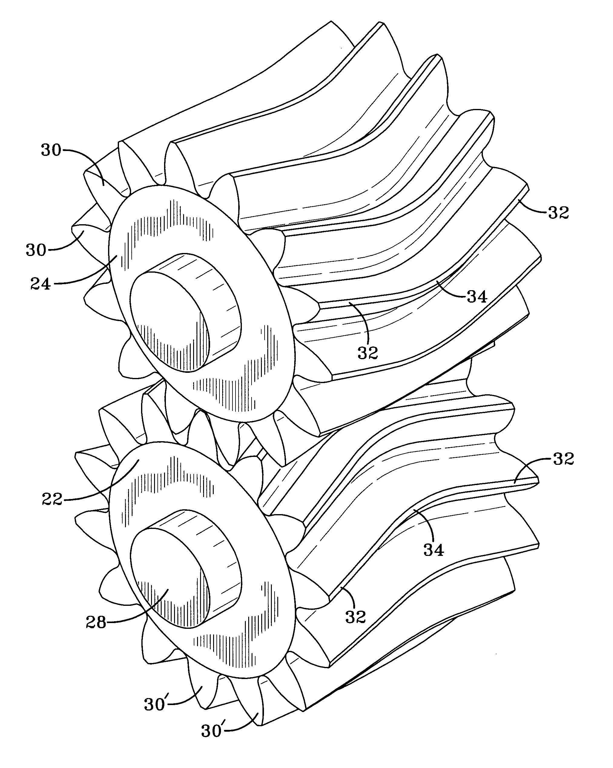
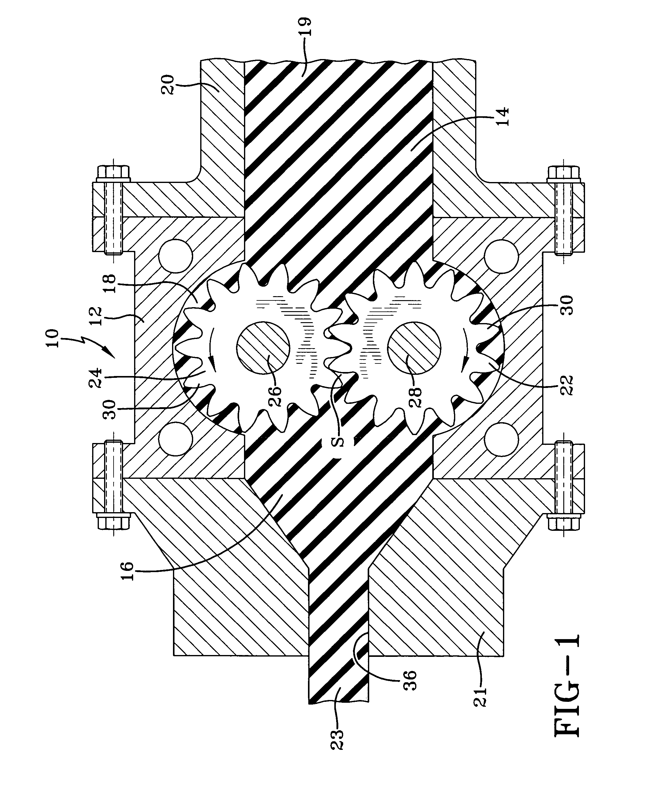
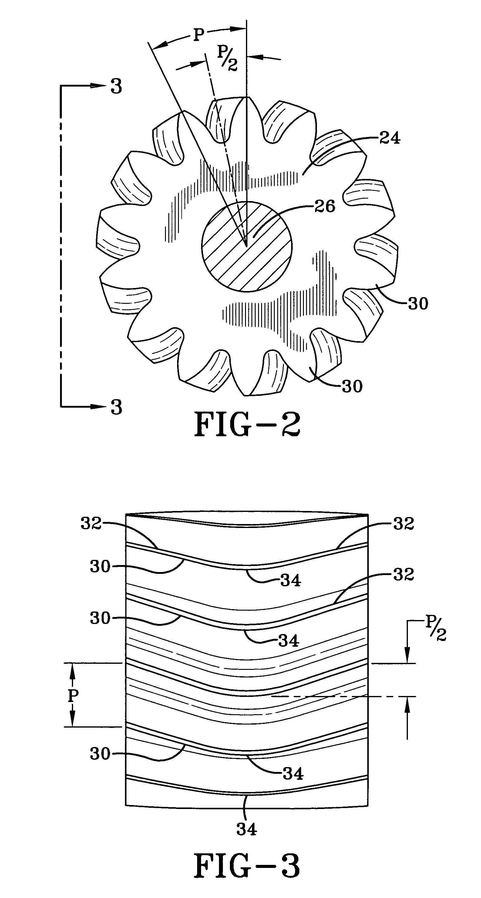
[0017]Referring now to the drawings wherein the showings are for the purpose of illustrating a preferred embodiment of the invention only and not for the purpose of limiting the same, FIG. 1 is a cross sectional view of a gear pump 10 having a housing 12 containing an inlet chamber 14, an outlet chamber 16, and a metering chamber 18. The housing 12 may be connected to a source for supplying elastomeric material 19 such as an extruder 20 (not shown) at the inlet chamber. The outlet chamber 16 may also be in communication with a shaping member such as a die 21 or other non-resilient means for shaping a tire component 23. Mounted in the housing 12 are two gears 22,24 in meshing engagement. The gears 22,24 have shafts 26,28 rotatably mounted in the housing 12 and one of the shafts, or both shafts, may be driven to rotate the gears 22,24 in such a manner as to carry the elastomeric material 19 fed into the inlet chamber 14 through the metering chamber 18 into the outlet chamber 16.

[0018]...


PUM

PropertyMeasurementUnit
distanceaaaaaaaaaa
elastomericaaaaaaaaaa
pressureaaaaaaaaaa

Abstract

A gear pump and method for pumping elastomeric material having two gears with meshing herringbone gear teeth. Each of the gear teeth has helical side portions and a curved central portion which extends circumferentially of the gear a distance equal to at least one half the pitch of the gear teeth to provide a continuous squeezing contact between the teeth of the two gears for pumping a uniform strip of elastomeric material from the gear pump.

Description

BACKGROUND OF THE INVENTION[0001]1. Field of Invention[0002]This invention relates to a gear pump for feeding an elastomeric material to a die providing components for building a tire. The gear pump of this invention is especially useful in minimizing the temperature differential across the face of the gears and avoiding pressure spikes experienced with herringbone gear teeth. The pumped material is also metered without causing pulsations such as those experienced during unloading a gear pump with spur gear teeth.[0003]2. Description of the Related Art[0004]Gear pumps such as those shown in U.S. Pat. No. 5,267,847 have been proposed for extruding strips of rubber for tire components wherein the gears are spur gears. The spur gears have caused the rubber to be ejected from the gear pump with pulsations corresponding to the pumping action of the axially oriented spaced gear teeth. This results in extruded components which are not uniform and do not meet the specifications for building...

Claims


Application Information

Patent Timeline
Patent Type & Authority Patents(United States)
IPC IPC(8): F01C1/16B29C48/07B29C48/37B29C48/38B29C48/465B29C48/92F04C2/08F04C2/18F04C13/00F04C15/00
CPCB29C47/367B29C47/92F04C2/086F04C2/18F04C13/002F04C15/0049B29C47/364B29C47/0019B29C47/522B29C2947/92514B29C2947/9259B29C2947/92885F04C15/0042B29K2021/00B29C48/92B29C48/07B29C48/37B29C48/387B29C48/465B29C2948/92514B29C2948/9259B29C2948/92885
Inventor NICOLAS, BERNARDBURG, GARY ROBERTMARSHALL, MALCOLM GEORGE
Owner THE GOODYEAR TIRE & RUBBER CO
Why Eureka
Try Eureka