Wave energy conversion system

a technology of energy conversion system and wave energy, which is applied in the direction of sea energy generation, dynamo-electric machines, electrical apparatus, etc., can solve the problems of increasing drag, achieve the effects of reducing wear, improving energy recovery efficiency, and extending the life of components

Inactive Publication Date: 2006-05-09
SEAWOOD DESIGNS
View PDF9 Cites 56 Cited by
  • Summary
  • Abstract
  • Description
  • Claims
  • Application Information

AI Technical Summary

Benefits of technology

[0036]A float that is basically a closed rectangular tube with rounded corners operates a hydraulic cylinder to pressurize a fluid that in turn is used to create heat, pump fluids, or more commonly, provide mechanical energy to operate equipment such as electrical generators. The rod of the hydraulic cylinder is attached to the float near the center of the float. The lower end of the hydraulic cylinder is anchored to the seabed. The hydraulic cylinder is the only mooring connection the float has with the seabed. The float is free to rotate in the plane of the surface of the sea and naturally tends to align its long axis parallel with the crest of incoming waves. The system is therefore omni-directional providing the ability to optimally extract energy from waves emanating from all directions. It may be advantages in some circumstances to angle the ends of the float to somewhat face oncoming waves to reinforce the natural tendency of the float to align itself parallel with wave crests. Other means such as fins (similar to the rudder on an airplane) can also be used to encourage the float to stay aligned with the wave crests if required.
[0037]Relative geometry of the installed system components and configuration of the components themselves are selected in a way to encourage the float to move horizontally (surf) as well as move upward due to the action of an oncoming wave. The surfing action improves the energy yield of the system. The system is designed to operate in the “surf zone” to take advantage of the system's ability to surf the steeper waves prevalent in the surf zone. A recovery force is applied to the float after each wave has passed to bring it back to the starting position before the next wave begins to build.

Problems solved by technology

With this arrangement the cylinder rod is made hollow and is used to make the hydraulic connection with the float without the use of flexible hose that is very expensive and bulky that in turn increases drag that is undesirable during the return of the float to the starting position.

Method used


Image

  • Wave energy conversion system
  • Wave energy conversion system
  • Wave energy conversion system

Examples


Embodiment Construction

[0055]In order to more clearly understand the present invention part numbers as assigned in the following parts list will be used:

[0056]

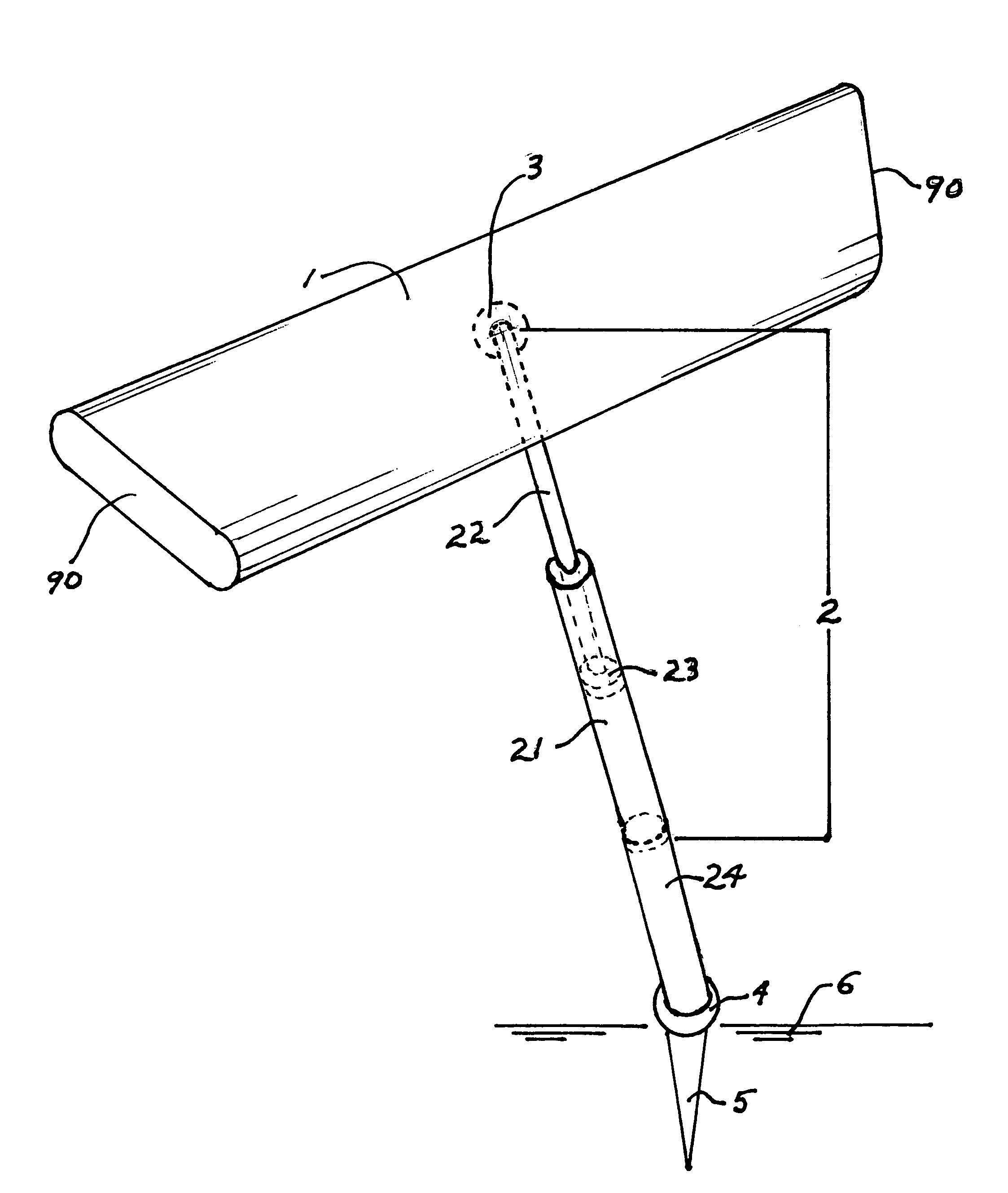
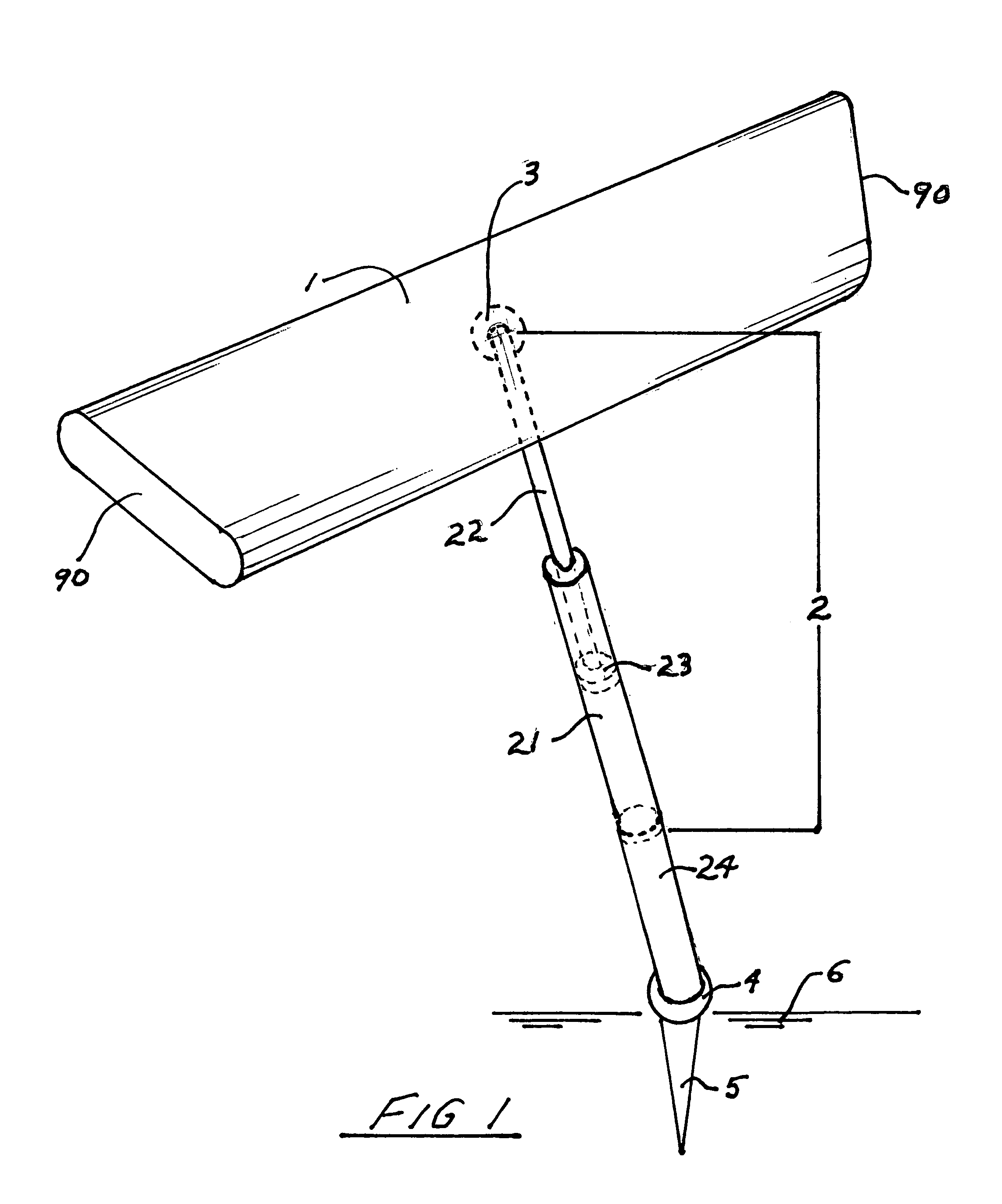
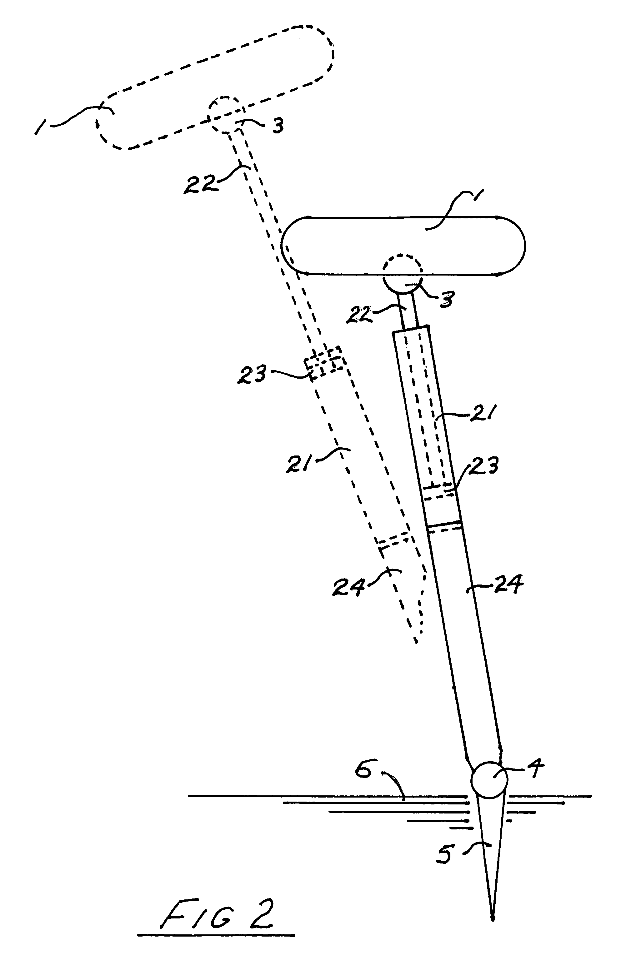
Part NumberDescription1Float2Hydraulic Cylinder Assembly3Flexible Joint at Float4Flexible Joint at Seabed5Seabed Anchor6Seabed21Barrel22Hollow Cylinder Rod23Piston24Extension Tube25Hydraulic Fluid26Ports71Hydraulic Accumulator72Check Valve73Adaptive Control74Variable Displacement Motor75Electric Generator76Fluid Cooler80Low Pressure Hydraulic Accumulator81Check Valve82Fluid Reservoir83Small Pump84 / 85Shut Off Valves90Float Ends

[0057]A large float 1 as shown in FIG. 1 designed to be as light as possible and still withstand the crushing pressures associated with submergence to a substantial depth that typically might be 25 feet or more. The ends 90 of the float are angled to face oncoming waves.

[0058]A hydraulic cylinder assembly 2 is attached near the center of the float by means of a flexible joint 3 designed to withstand high tensile loads and is ma...


PUM


Abstract

An omni-directional system configured to convert the kinetic and potential energy in ocean waves to electrical energy or in some special cases to other forms of energy such as heat, mechanical and pressure energy. The system employs a float moored by a single hydraulic cylinder anchored to the seabed. Wave energy is captured as the float is displaced vertically and horizontally in response to wave action extending the hydraulic cylinder that in turn forces fluid under high pressure to the float where appropriate valves, hydraulic accumulators, and variable displacement hydraulic motors are arranged to drive electric generators. A secondary benefit of the system is the reduction of near shore erosion.

Description

FIELD OF INVENTION[0001]Systems designed to extract kinetic and potential energy from ocean waves and convert this energy to a form useful to mankind. The desired output of these systems is usually electrical energy but other outputs can be used in special circumstances such as mechanical energy for pumping and operating process equipment. Heat energy and pressure energy can also be valuable outputs.BACKGROUND OF THE INVENTION[0002]Mankind has realized for a very long time that ocean waves contain considerable amounts of energy that could be very useful if a means was available to harness it. In recent times, wave energy measurements have been undertaken by a number of countries. It has been found that a number of sites have an annual average wave energy flux approaching 70 kW per meter of wave crest. This level of energy concentration presents a very exciting opportunity to provide renewable “green” energy in very significant amounts. A mile of shoreline with an annual average ener...

Claims


Application Information

Patent Timeline
Patent Type & Authority Patents(United States)
IPC IPC(8): F03B13/10F03B13/12F03B13/18H02P9/04
CPCF03B13/187Y02E10/38Y02E10/30
Inventor WOOD, CHARLES
Owner SEAWOOD DESIGNS
Why Eureka
Try Eureka