Driver circuit for LED vehicle lamp

a technology of led vehicle lamps and driver circuits, which is applied in the direction of electric variable regulation, process and machine control, instruments, etc., can solve the problems of low efficiency, cumbersome current regulation, switching noise and cost,

Active Publication Date: 2006-05-09
OSRAM SYLVANIA INC
View PDF5 Cites 73 Cited by
  • Summary
  • Abstract
  • Description
  • Claims
  • Application Information

AI Technical Summary

Benefits of technology

[0008]Accordingly, it is therefore an object of this invention to provide a driver circuit for a high efficiency LED Vehicle Lamp with low switching noise having TAIL and STOP modes of operation.
[0010]It is yet another object of this invention to sense low input voltage and reconfigure the LED strings to maintain continued operation with legal light intensity.

Problems solved by technology

When LEDs are used in higher power applications such as the rear combination lights (STOP / TURN / TAIL), lower efficiency, cumbersome current regulation, switching noise and cost have been problems along with a desire to operate over a reduced input voltage range.
However, this switching driver circuit produces unwanted switching noise and does not have a TAIL light capability.
However, hard switching of the LEDs ON and OFF occurs which causes switching noise to be generated and the switching noise makes it difficult to meet automotive requirements for radiated and conducted emissions.

Method used


Image

  • Driver circuit for LED vehicle lamp
  • Driver circuit for LED vehicle lamp
  • Driver circuit for LED vehicle lamp

Examples


first embodiment

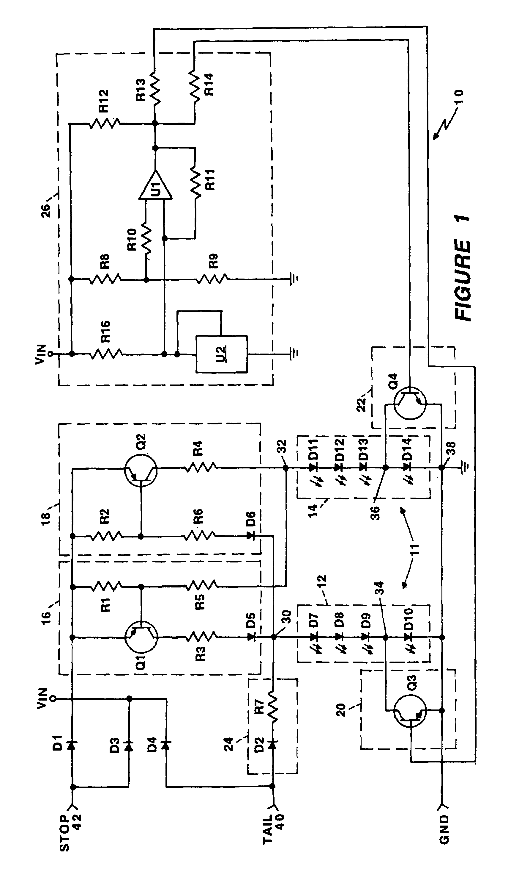
[0019]Referring to FIG. 1, a schematic diagram of a vehicle lamp driver circuit 10 is shown for driving an array 11 of light emitting diodes (LEDs) according to the present invention. The driver circuit 10 provides current via first LED Driver 16 and second LED driver 18 to an array 11 of LEDs arranged in two rows of four series connected LEDs, LED strings 12 and 14. The driver circuit 10 receives two control inputs, TAIL 40 (for tail lights) and STOP 42 (for stop lights), and has four output connections 30, 32, 34, 36 for connecting to the first LED string 12 and second LED string 14. The Tail 40 input causes the driver circuit 10 to operate in a TAIL mode, and the STOP 42 input causes the device circuit to operate in a STOP mode.

[0020]The first LED string 12 comprises four LEDs D7, D8, D9, and D10 connected in series. The series connections are from cathode to anode with the cathode of the last LED D10 connected to the common ground lead of a motor vehicle and the driver circuit c...

second embodiment

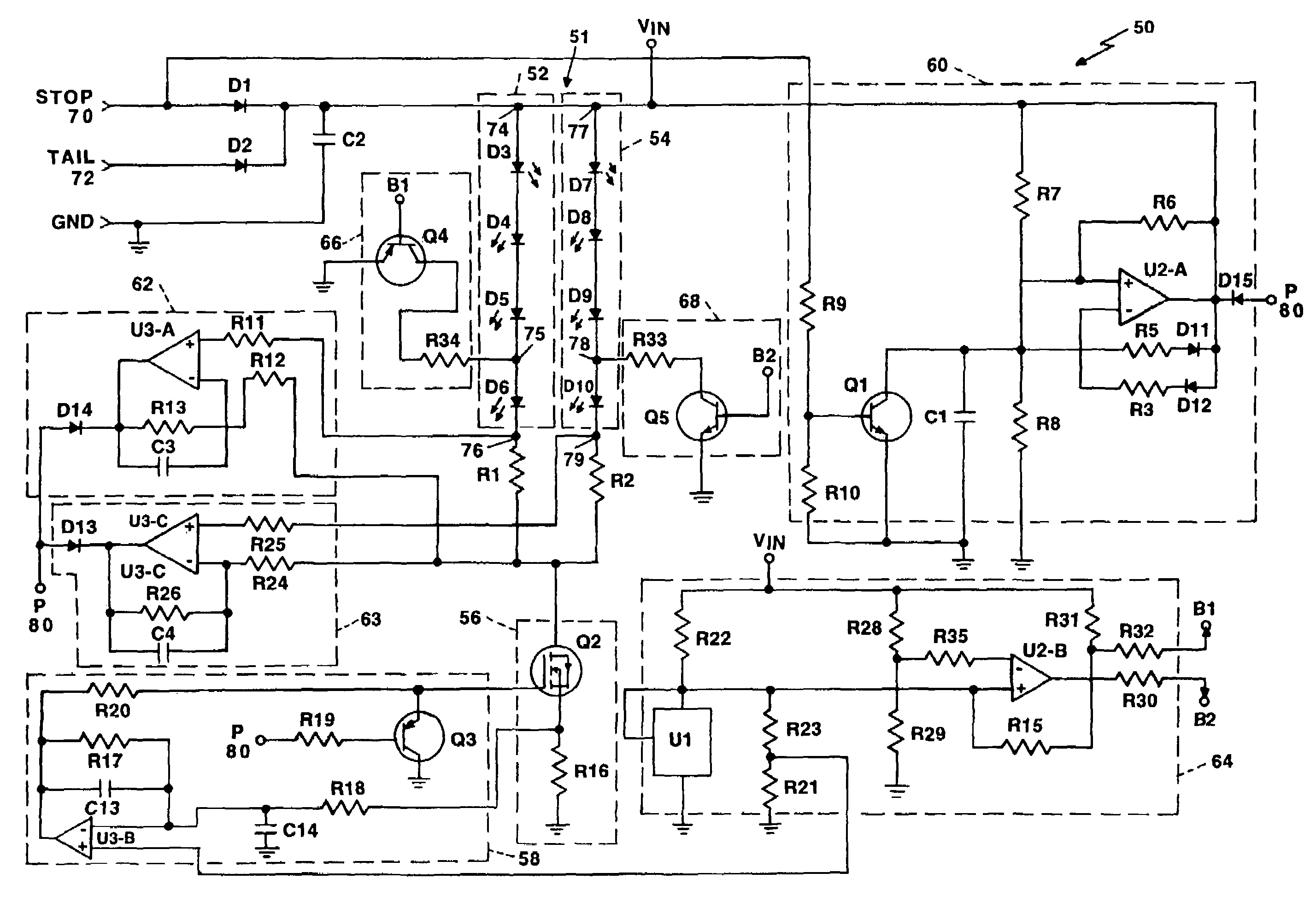
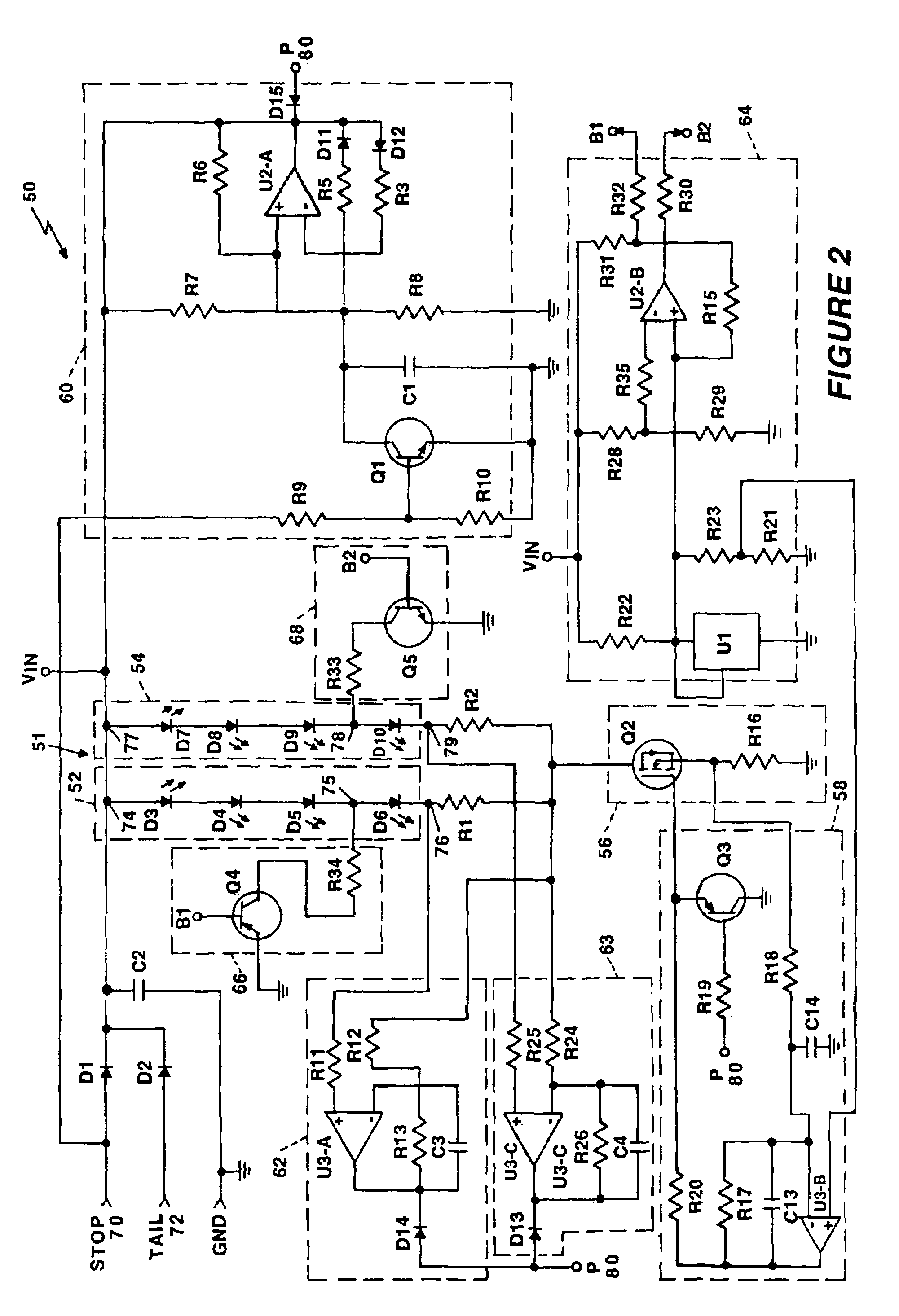
[0032]Referring now to FIG. 2, a schematic diagram of a vehicle lamp driver circuit 50 is shown for driving an array 51 of light emitting diodes (LEDs) arranged in two rows of 4 series connected LEDs according to the present invention. The driver circuit 50 provides linear regulation of current passing through a first LED string 52 and a second LED string 54. The driver circuit 50 receives two control input signals, STOP 70 and TAIL 72, and has six output connections 74–79 for connecting to the first LED string 52 and the second LED string 54. STOP 70 input causes the driver circuit 50 to operate in a linear mode whereby the current passing through the first LED string 52 and the second LED string 54 stays steady in a linear mode of operation. The TAIL 72 input causes the driver circuit 50 to operate in a pulsed mode whereby an average linear current passes through the first LED string 52 and the second LED string 54 resulting in the light output intensity of the LED array 51 in the...


PUM


Abstract

A first vehicle lamp driver circuit for a light emitting diode (LED) array, the LED array having a first string of four LEDs in series and a second string of four LEDs in series. A first LED driver drives the first LED string and a second LED driver drives the second LED string. In a STOP mode of operation, the current to both LED strings is controlled by the LED driver in series with the LED string. In a TAIL mode of operation, the current is provided to only one LED string via a series connected diode and resistor. When there is reduced input voltage, operation of the LED strings is provided by switching circuits that short-out one LED in each LED string. A second vehicle lamp driver circuit comprises a first LED string and a second LED string in series with a control switch having a feedback circuit for maintaining constant current regulation to control the sum of the current in each LED string and reduce switching noise.

Description

CROSS-REFERENCE TO RELATED APPLICATIONS[0001]This is a non-provisional Patent Application claiming priority of provisional application for patent No. 60 / 498,244 filed Aug. 27, 2003.BACKGROUND OF THE INVENTION[0002]1. Field of the Invention[0003]This invention relates generally to light emitting diodes (LEDs) used in light sources in automobiles and other vehicles, and in particular to a driver circuit that provides linear regulated current and reduced input voltage operation.[0004]2. Description of Related Art[0005]Advances in light emitting diodes (LEDs) have made LEDs very attractive for use in vehicles because of their long operation life, higher efficiency and low profile. LED light output is proportional to the LED current, and therefore, a current source is the preferred method of driving the LEDs. When LEDs are used in higher power applications such as the rear combination lights (STOP / TURN / TAIL), lower efficiency, cumbersome current regulation, switching noise and cost have ...

Claims


Application Information

Patent Timeline
Patent Type & Authority Patents(United States)
IPC IPC(8): H05B37/02H05B37/00H05B44/00B60Q1/30B60Q1/44H01L
CPCB60Q1/30B60Q1/44H05B33/0812H05B33/089H05B33/083Y02B20/345Y02B20/343H05B45/48H05B45/54B60Q1/303
Inventor MADHANI, VIPINJOHNSEN, ANDREW O.
Owner OSRAM SYLVANIA INC
Why Eureka
Try Eureka