
Disk drive head resetting system using slider heater

a slider heater and head technology, applied in the field of disk drives, can solve the problems of misalignment of the magnetic orientation of one of the head's components, excessive electrical stress, and damage to the disk drive head,

Active Publication Date: 2006-05-09
MAXTOR
View PDF7 Cites 32 Cited by
  • Summary
  • Abstract
  • Description
  • Claims
  • Application Information

AI Technical Summary

Benefits of technology

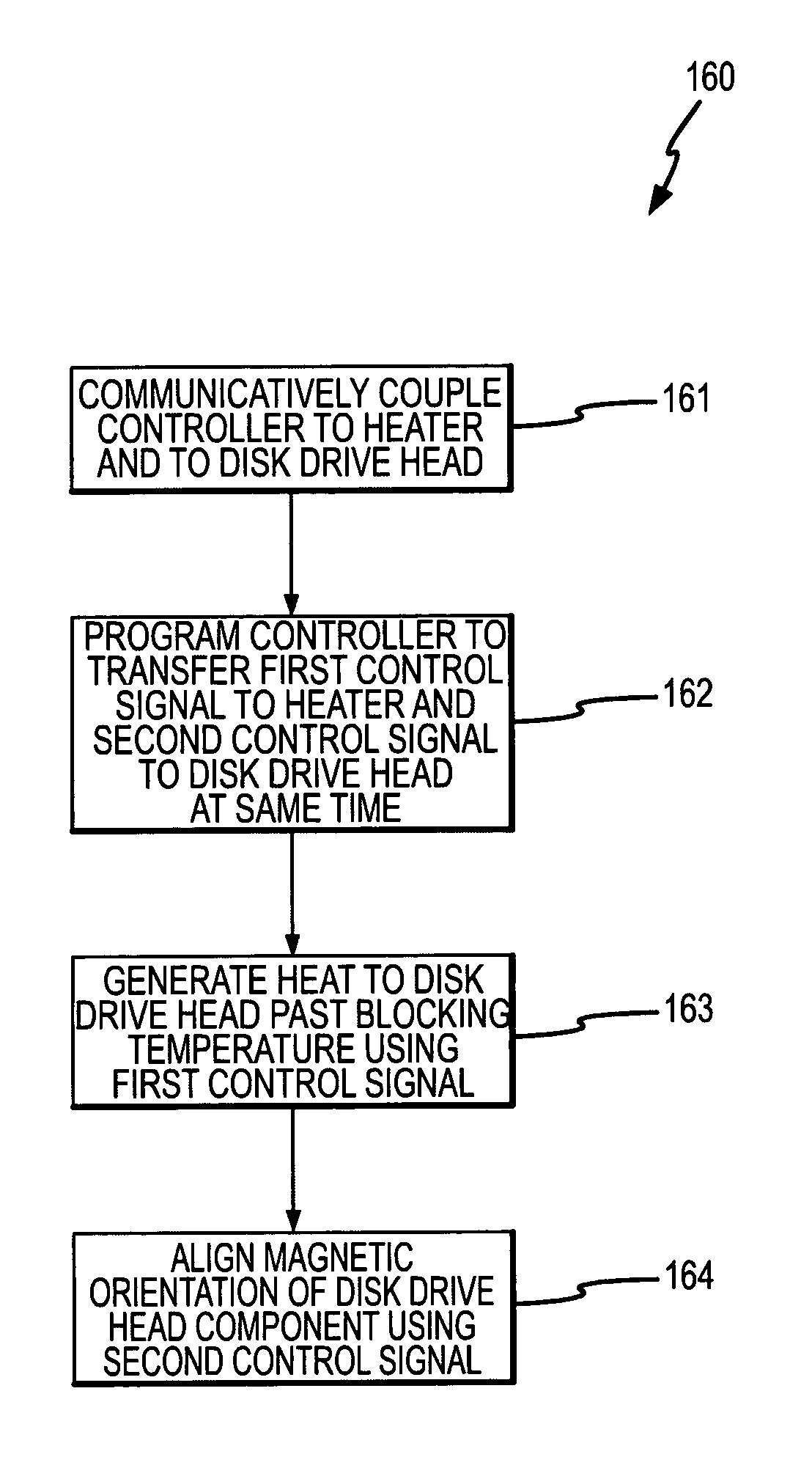
[0010]The head resetting system may be used at any appropriate time. For instance, the head resetting system may be used during the initial manufacture or assembly of a disk drive. The disk drive head reset of the present invention may also be used to provide the initial magnetization for the head, and may also be used to reset the magnetization of for the head (e.g., when the disk drive head becomes misaligned during some part of the manufacturing / assembly process due to, for example, ESD). Both are considered as “establishing” the magnetic orientation in the case of the first aspect. The head resetting system also may be used after the various components of the disk drive had been enclosed (e.g. disposed between a cover that is detachably interconnected with a base plate), and including after the disk drive has been incorporated into a computer. For instance, a head resetting operation could be undertaken on some periodic or programmed basis after a disk drive has been integrated into a computer, on an “as needed” basis, or both. Typically the head resetting function will be undertaken when the head is parked and when any disk used by the disk drive has quit rotating. The first control signal may then be sent to the heater and the second control signal may be sent to the disk drive head at substantially the same time, as described hereinabove, to reset the disk drive head. With the disk drive head having been reset, read and write operations of the disk drive may resume with improved data quality.
[0015]In one embodiment of the invention, the heat is used to substantially free a magnetic orientation of a disk drive head component. The second control signal may be used to align a magnetic orientation of the disk drive head component. For example, the disk drive head component may be a pinned layer of the disk drive head. The heater may be of any appropriate type that passively heats the disk drive head (or another component thereof, such as an antiferromagnetic pinning layer) past a blocking temperature (e.g., to a temperature of at least about 20° Celsius) of the disk drive head component to substantially free a magnetic orientation of the component.

Problems solved by technology

Disk drive heads are sensitive devices that can be damaged through excessive use and / or excessive electrical stress (e.g., electrostatic discharge, or “ESD”).
Head damage may include a misalignment of the magnetic orientation of one the head's components, or layers.
Excessive use and / or excessive electrical stress have a tendency to misalign the magnetic orientation of the pinned layer of the head.
When the magnetic orientation of the pinned layer of the head becomes misaligned with respect to an optimal magnetic orientation, detection of magnetic impressions on the disk may be impaired and data quality may degrade.
However, as disk drive head sizes have decreased in an effort to enhance / accommodate increased data storage capacity of the disk drive, the disk drive heads have become increasingly sensitive to certain electrical effects.
Because smaller disk drive heads are more electrically sensitive than larger disk drive heads, pulsed electric current methods often exacerbate the problem of magnetic alignment by causing physical damage to the disk drive head, which may not be repairable.

Method used


Image

  • Disk drive head resetting system using slider heater
  • Disk drive head resetting system using slider heater
  • Disk drive head resetting system using slider heater

Examples


Embodiment Construction

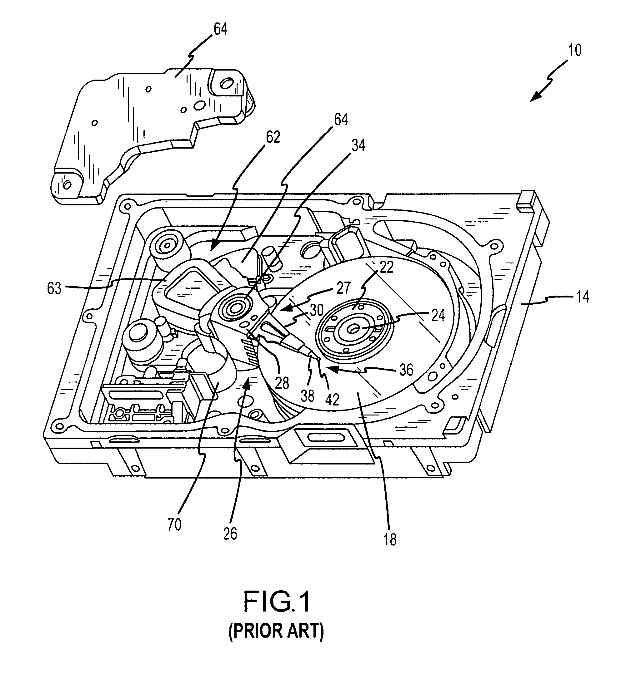
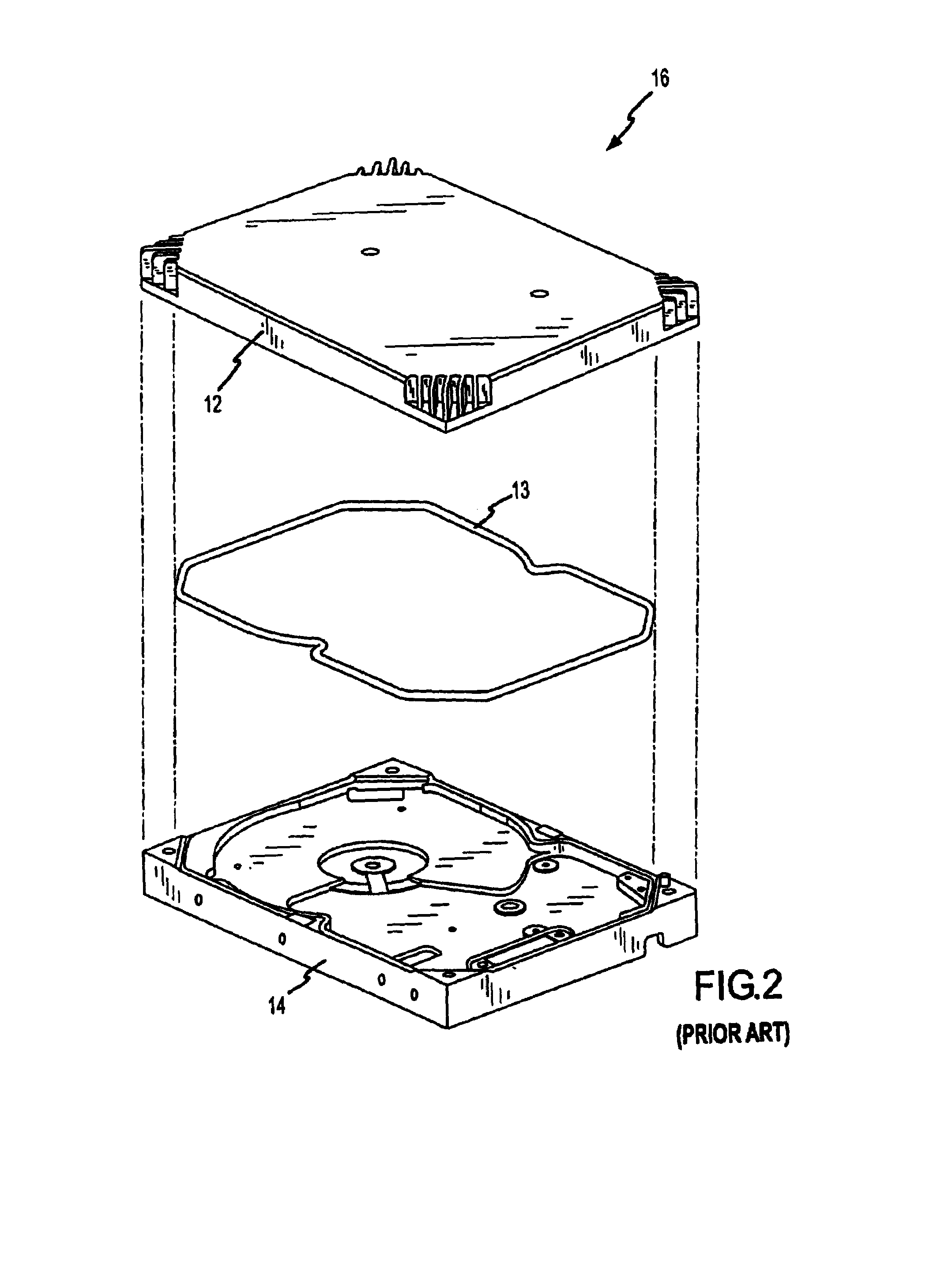
[0036]One embodiment of a prior art disk drive 10 is illustrated in FIGS. 1–4. However, this disk drive 10 may be adapted to incorporate a disk drive head resetting system in accordance with FIGS. 6A–8 that will be discussed below, such an adaptation not being known to be within the prior art. The disk drive 10 generally includes a disk drive housing 16 of any appropriate configuration that defines an enclosed space for the various disk drive components. Here the housing 16 includes a base plate 14 that is typically detachably interconnected with a cover 12. A suitable gasket 13 may be disposed between the cover 12 and the base plate 14 to enhance the seal therebetween.

[0037]The disk drive 10 includes one or more data storage disks 18 of any appropriate computer-readable data storage media. Typically both of the major surfaces of each data storage disk 18 include a plurality of concentrically disposed tracks for data storage purposes. Each disk 18 is mounted on a hub by a disk clamp...


PUM


Abstract

The invention is generally directed to a disk drive head resetting system. The system has a slider with a disk drive head associated therewith. The disk drive head may be on the slider and affixed thereto. A heater is also associated with a slider and spaced apart from the disk drive head. A controller is communicatively coupled to the heater and to the head to transfer a first control signal to the heater and a second control signal to the disk drive head at substantially the same time. The first control signal may be used to generate heat past a blocking temperature of the head to substantially free a magnetic orientation of the head. While the first control signal is being transferred to the heater, a second control signal is transferred to the disk drive head to align a magnetic orientation of the head to a desired magnetic orientation.

Description

CROSS REFERENCE TO RELATED APPLICATIONS[0001]This patent application claims priority under 35 U.S.C. §119(e) to U.S. Provisional Patent Application Ser. No. 60 / 542,645, that was filed on Feb. 5, 2004, that is entitled “RESETTING OF MAGNETIC HEADS USING BUILT-IN HEATER AND CURRENT OR A MAGNETIC FIELD,” and the entire disclosure of which is hereby incorporated by reference in its entirety herein.FIELD OF THE INVENTION[0002]The present invention generally relates to the field of disk drives and, more particularly, to a system that resets a magnetic disk drive head using a heater that is not part of the disk drive magnetic head.BACKGROUND OF THE INVENTION[0003]Disk drive heads are sensitive devices that can be damaged through excessive use and / or excessive electrical stress (e.g., electrostatic discharge, or “ESD”). Head damage may include a misalignment of the magnetic orientation of one the head's components, or layers. For example, a pinned layer of the head is intended to maintain a...

Claims


Application Information

Patent Timeline
IPC IPC(8): G11B21/02
CPCG11B5/6005G11B5/465G11B5/314G11B5/607G11B5/40
Inventor BARIL, LYDIASTROM, BRIAN
Owner MAXTOR
Learn More