
Retaining flag value associated with dead result data in freed rename physical register with an indicator to select set-aside register instead for renaming

a flag value and dead result technology, applied in the field of microprocessors, can solve the problems of flag bits involved in flags, other hazards may be present, complicating the freeing of physical registers in the register renaming mechanism,

Active Publication Date: 2006-05-09
MEDIATEK INC
View PDF45 Cites 20 Cited by
  • Summary
  • Abstract
  • Description
  • Claims
  • Application Information

AI Technical Summary

Benefits of technology

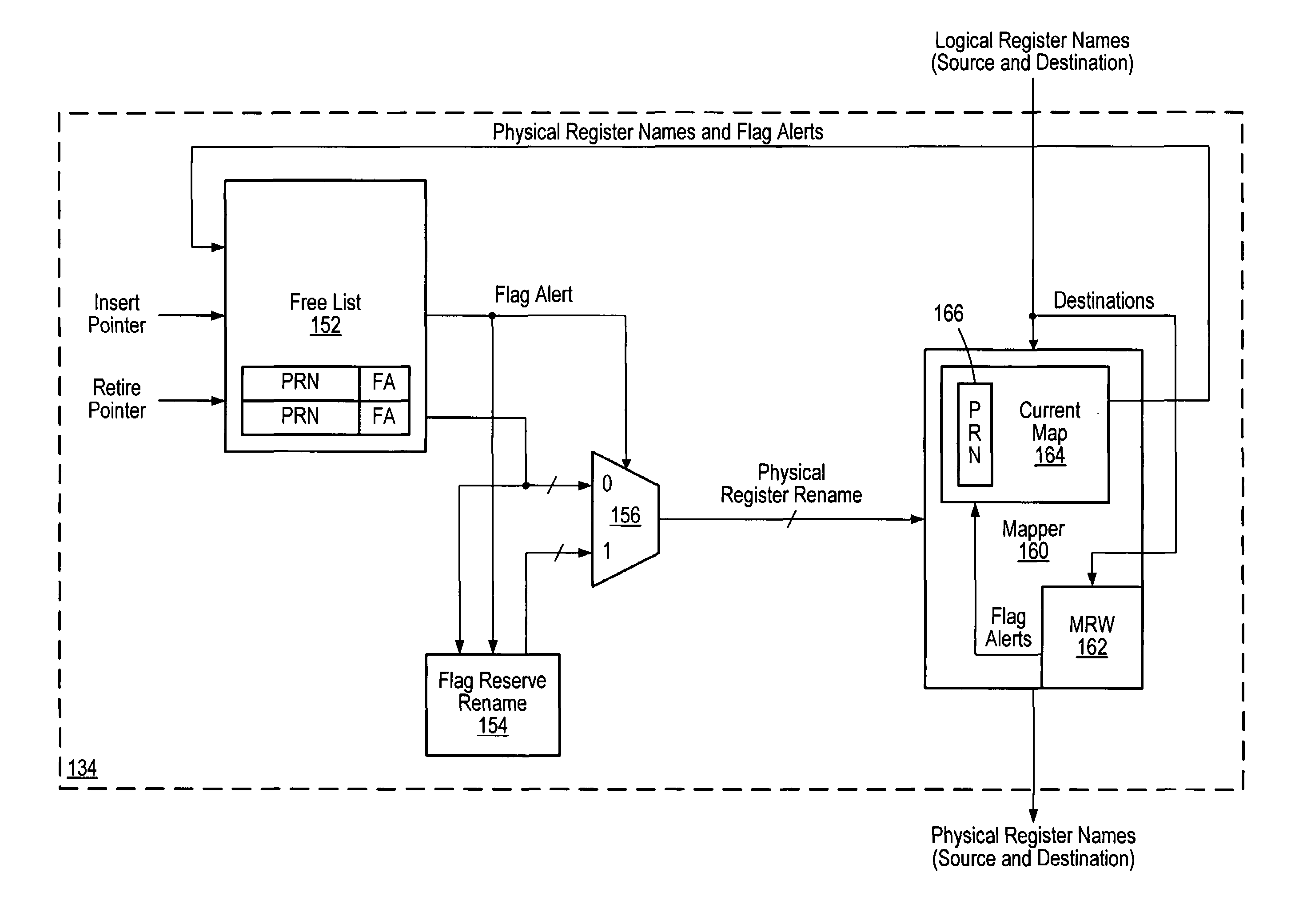
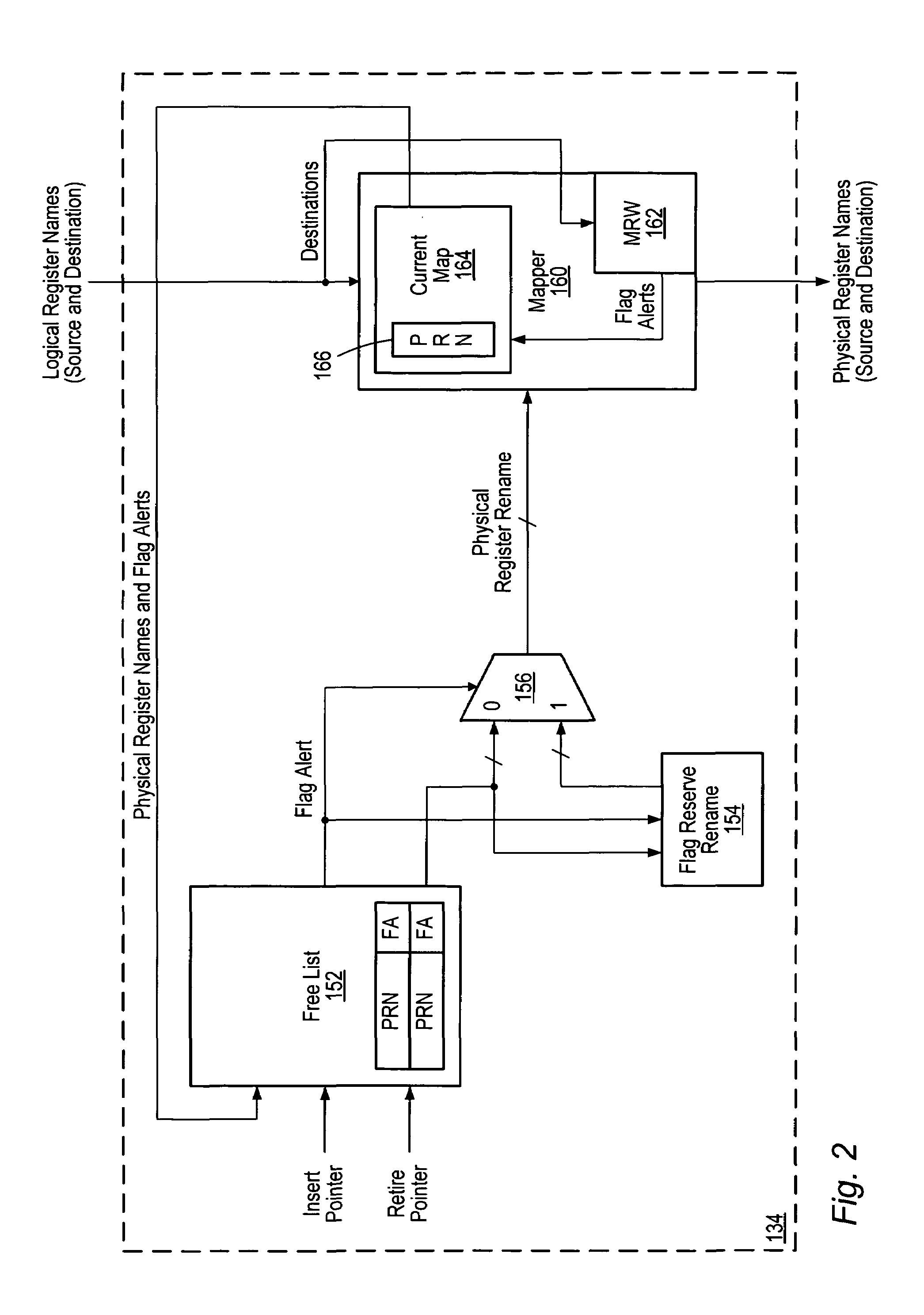
The patent describes a method and apparatus for retaining flag values when an associated data value dies. The system includes two storage circuits: a free list and a set of indications. The free list stores a list of physical register names and indications of whether or not a physical register associated with a physical register name was assigned to store a logical register result and flag results of a previous instruction. The set of indications includes one or more physical register names separate from the free list. The system also includes a selection circuit that receives a first indication and provides the first register name to a mapper for assignment to a logical register if the first indication is in a first state. The system also includes a second physical register name that may be provided to the mapper if the first indication is in a second state. The technical effect of this patent is to improve the efficiency and accuracy of a computer system by optimizing the use of physical registers and flag values.

Problems solved by technology

Although register renaming may allow instructions to be executed out of order without overwriting older register results, other hazards may be present.
One such hazard involves the flag bits (e.g., carry, overflow, etc.).
If the same physical register stores both a logical register value and a flags value, the above situation may complicate the freeing of physical registers in the register renaming mechanism.

Method used


Image

  • Retaining flag value associated with dead result data in freed rename physical register with an indicator to select set-aside register instead for renaming
  • Retaining flag value associated with dead result data in freed rename physical register with an indicator to select set-aside register instead for renaming
  • Retaining flag value associated with dead result data in freed rename physical register with an indicator to select set-aside register instead for renaming

Examples


Embodiment Construction

Processor Overview

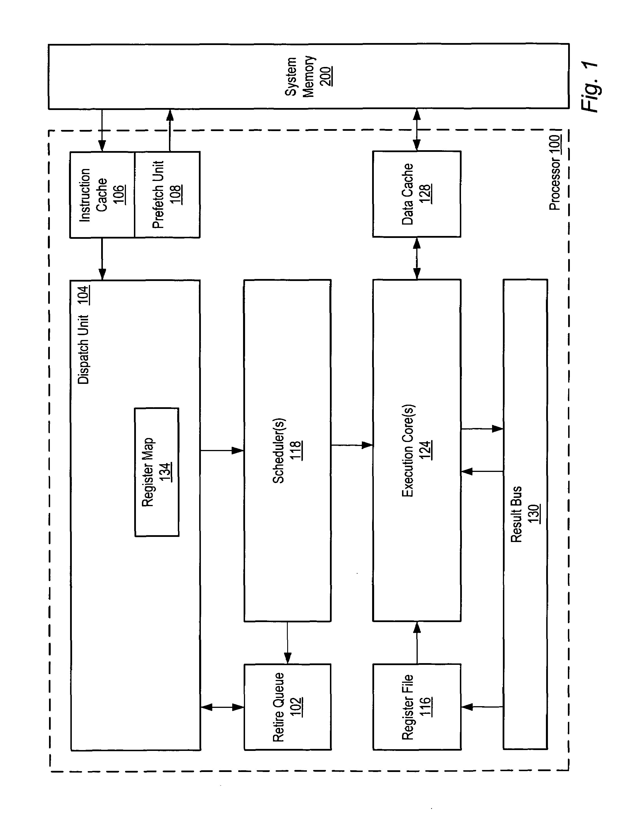
[0018]FIG. 1 is a block diagram of one embodiment of a processor 100. The processor 100 is configured to execute instructions stored in a system memory 200. Many of these instructions operate on data stored in the system memory 200. It is noted that the system memory 200 may be physically distributed throughout a computer system and / or may be accessed by one or more processors 100.

[0019]In the illustrated embodiment, the processor 100 may include an instruction cache 106 and a data cache 128. The processor 100 may include a prefetch unit 108 coupled to the instruction cache 106. A dispatch unit 104 may be configured to receive instructions from the instruction cache 106 and to dispatch operations to the scheduler(s) 118. One or more of the schedulers 118 may be coupled to receive dispatched operations from the dispatch unit 104 and to issue operations to the one or more execution cores 34. The execution core(s) 124 may include one or more integer units, one or more...


PUM


Abstract

A method and apparatus for retaining flag values when an associated data value dies. A first storage circuit includes a free list for storing physical register names (PRNs) and indications indicative of whether a physical register associated with a PRN was assigned to store a logical register result and flag results of a first instruction and a logical register result and a subsequent instruction which overwrites the logical register result but not the flags. A second storage circuit stores PRNs separate from the free list. The first and second storage circuits output first and second PRNs to a selection circuit. If the first indication (associated with the first PRN) is in a first state, the selection circuit may provide the first PRN to a mapper for assignment to a logical register. If the first indication is in a second state, the second PRN may be provided to the mapper.

Description

BACKGROUND OF THE INVENTION[0001]1. Field of the Invention[0002]This invention is related to the field of microprocessors, and more particularly, the handling of flag values during the speculative execution of instructions.[0003]2. Description of the Related Art[0004]High performance microprocessors use various techniques to speed up the execution of instructions, including the speculative / out-of-order execution of instructions. Since speculatively executed instructions may update the registers in a microprocessor, a means for storing speculative results that may be written to the logical (architected) registers may be implemented.[0005]Register renaming is a technique used to keep track of speculative results that may be intended to be written to the logical registers. A microprocessor employing register renaming may include a physical register file which may store several copies of results intended for the logical registers. Each logical register may be associated with speculative...

Claims


Application Information

Patent Timeline
Patent Type & Authority Patents(United States)
IPC IPC(8): G06F9/38
CPCG06F9/3842G06F9/384
Inventor MCMINN, BRIAN D.PICKETT, JAMES K.ALSUP, MITCHELL
Owner MEDIATEK INC
Learn More