
System real-time analysis tool

Inactive Publication Date: 2006-05-09
BELL SEMICON LLC
View PDF12 Cites 32 Cited by
  • Summary
  • Abstract
  • Description
  • Claims
  • Application Information

AI Technical Summary

Benefits of technology

[0004]The present invention concerns an apparatus comprising a full system monitor. The monitor may be configured to monitor in real-time one or more (i) software variables down to change rates, (ii) hardware registers down to cycle rates, and (iii) firmware registers down to microcode fetch rates.
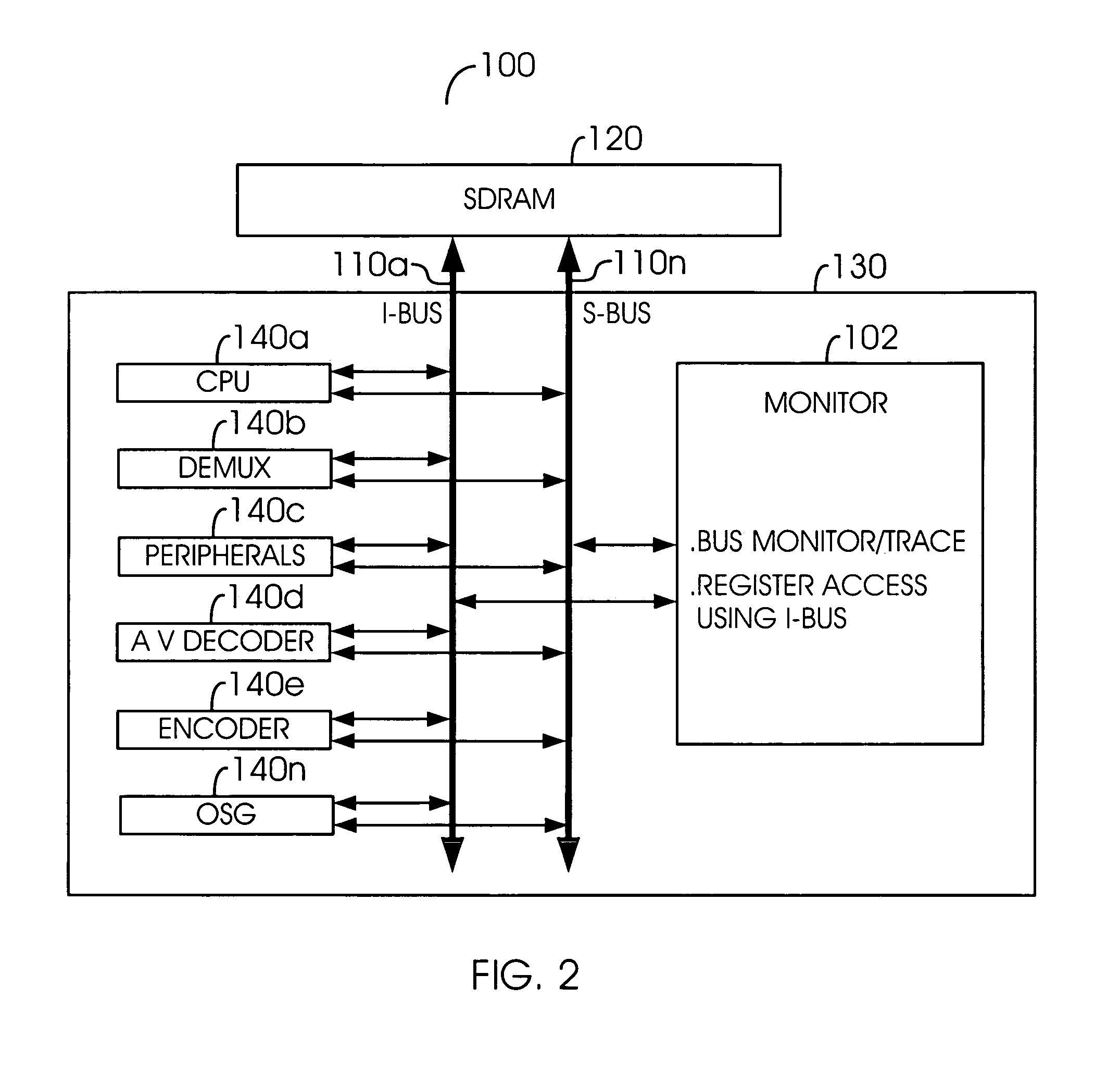
[0005]The objects, features and advantages of the present invention include providing a method and/or architecture for implementing complete real-time system analysis that may (i) provide real-time cycle-based register (or variable) access and coverage, (ii) provide non-intrusive register coverage, (iii) connect all address/data lines internally to the complete real-time system analysis tool and a system bus, (iv) provide a tool for real-time cycle-based or register-delta-based system trace/monitor/capture, (v) provide register level trace with software-defined trigger and depth, (vi) provide frequency of register use (e.g., for read and/or write access), (vii) provide timing between system events and/or register usage, (viii) provide system performance analysis including full system

Problems solved by technology

Conventional methods and / or architectures that provide complete system analysis do not provide the system analysis in real-time.
Conventional methods and / or architectures that provide real-time system analysis do not provide complete system analysis.

Method used


Image

  • System real-time analysis tool
  • System real-time analysis tool
  • System real-time analysis tool

Examples


Embodiment Construction

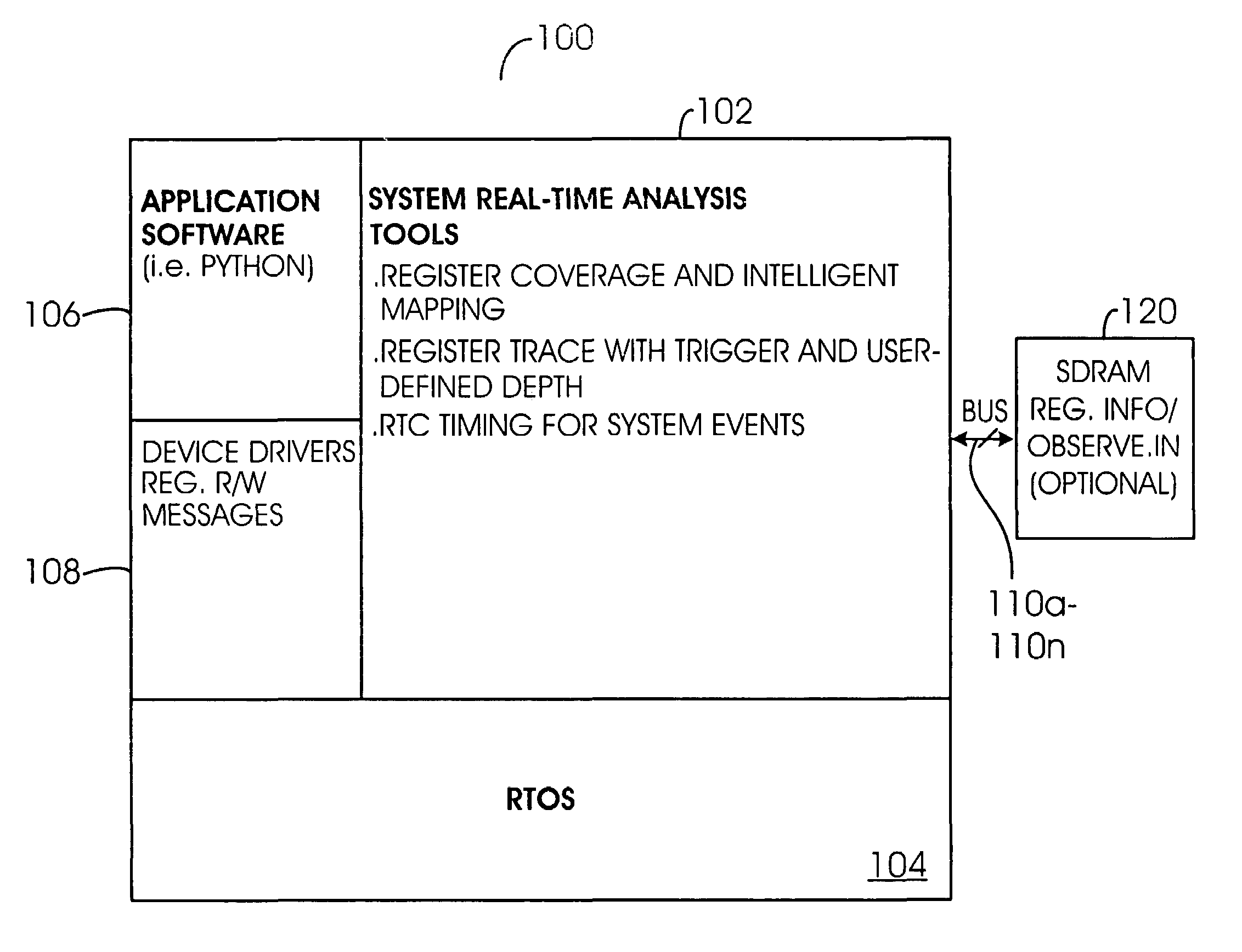
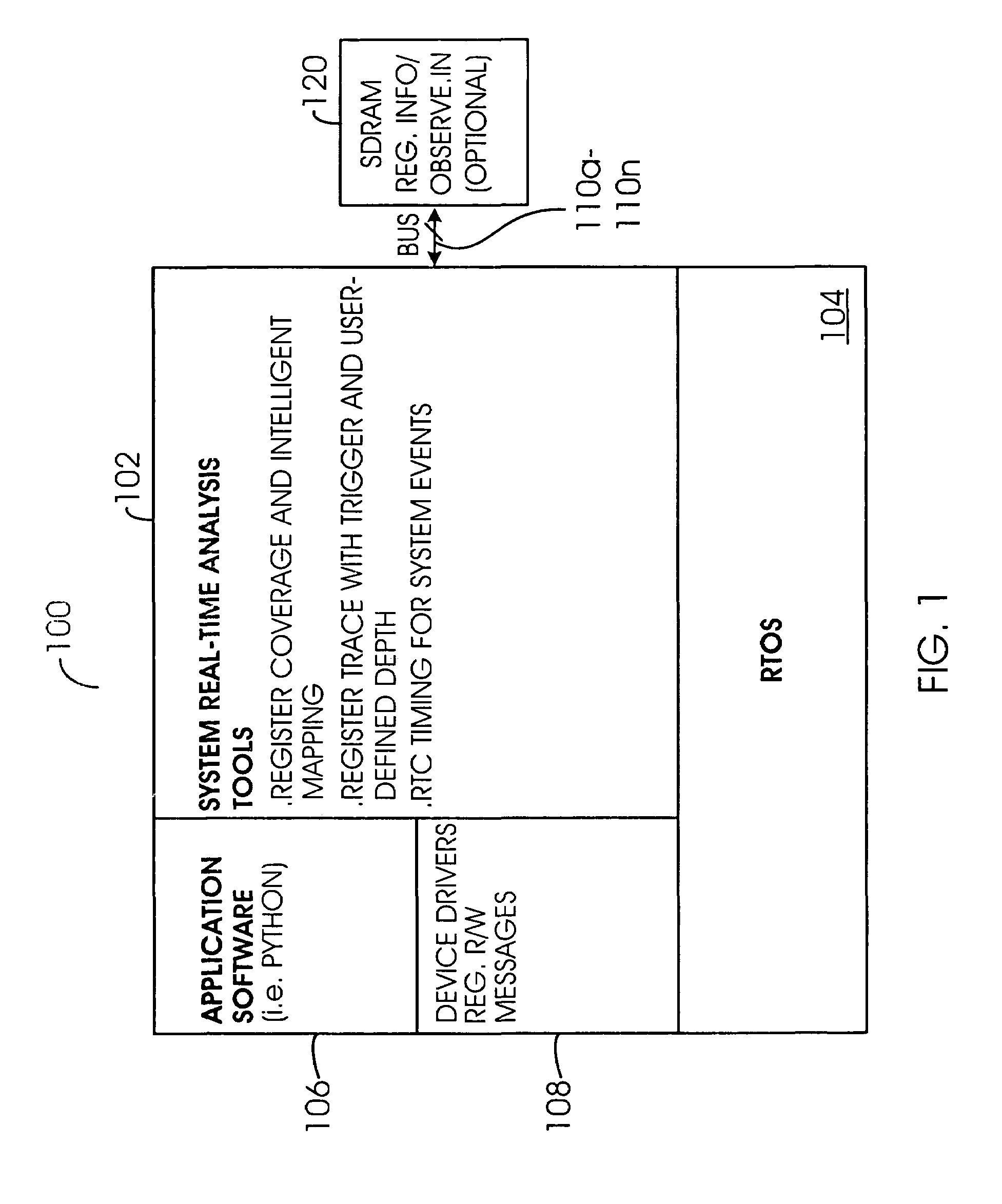
[0012]Referring to FIG. 1, a block diagram illustrating a system 100 is shown in accordance with a preferred embodiment of the present invention. In one example, the system 100 may be represented via software architecture. The system 100 may provide embedded complete real-time system analysis that includes hardware, software, and / or firmware register coverage and trace. The system 100 may be configured to provide complete real-time trace, monitor, and / or capture during normal, debug, and / or test operations. The system 100 may be configured to perform software and / or firmware trace to inline assembly codes. The system 100 may be implemented as a scalable architecture. The system 100 may be adaptable for implementation in any system (not shown) configured having one or more internal busses and hardware, software, and / or firmware registers. The system 100 may be configured to monitor in real-time one or more software variables, hardware registers, and / or firmware registers.

[0013]The sy...


PUM


Abstract

An apparatus comprising a full system monitor. The monitor may be configured to monitor in real-time one or more (i) software variables down to change rates, (ii) hardware registers down to cycle rates, and (iii) firmware registers down to microcode fetch rates.

Description

FIELD OF THE INVENTION[0001]The present invention relates to a method and / or architecture for implementing real-time system analysis generally and, more particularly, to a method and / or architecture for implementing complete real-time system analysis.BACKGROUND OF THE INVENTION[0002]Conventional methods and / or architectures that provide complete system analysis do not provide the system analysis in real-time. Conventional methods and / or architectures that provide real-time system analysis do not provide complete system analysis. Conventional methods and / or architectures for real-time system analysis have one or more of the following deficiencies (i) functioning of system level trace and coverage only, (ii) log files only on hardware and firmware register coverage, (iii) software register level trace is not known, (iv) unable to trace and cover every register within the system, (v) function level trace is not deep enough to provide an understanding of register level behavior, (vi) un...

Claims


Application Information

Patent Timeline
IPC IPC(8): G06F9/44
CPCG06F11/3636
Inventor AU, LAP-KIWATKINS, DANIEL
Owner BELL SEMICON LLC
Learn More