Pipeline protection system

a protection system and pipeline technology, applied in the direction of functional valve types, valve details, fluid removal, etc., can solve the problems of pipeline damage risk, electronic pressure sensors, and conventional hipps systems

Inactive Publication Date: 2006-05-16
GE OIL & GAS UK LTD
View PDF6 Cites 40 Cited by
  • Summary
  • Abstract
  • Description
  • Claims
  • Application Information

AI Technical Summary

Benefits of technology

[0006]It is an object of the present invention to provide a reliable protection system for a pipeline. This

Problems solved by technology

The conventional HIPPS system shown suffers from the drawback that it relies on electronic pressure sensors.
These

Method used


Image

  • Pipeline protection system
  • Pipeline protection system
  • Pipeline protection system

Examples


Embodiment Construction

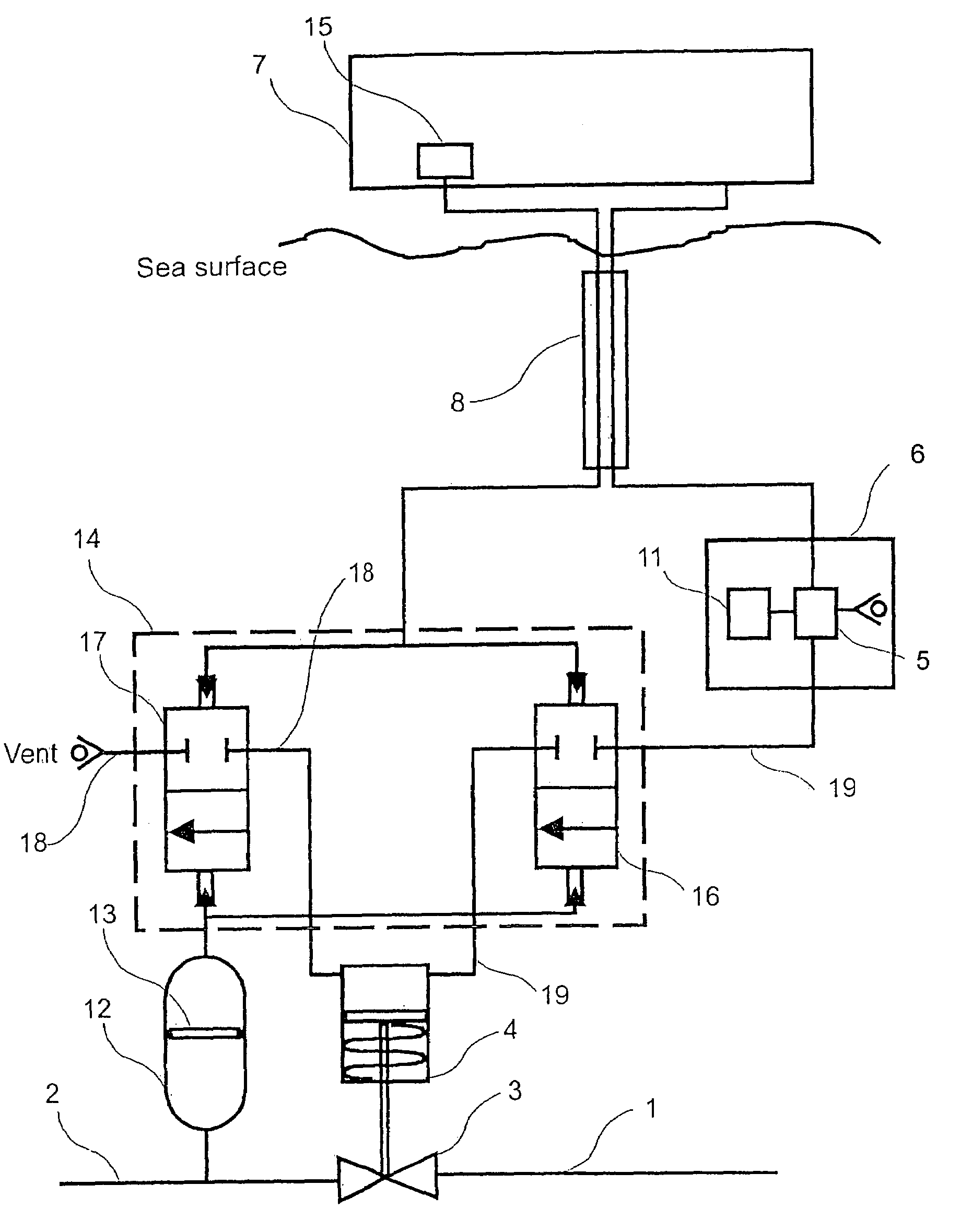
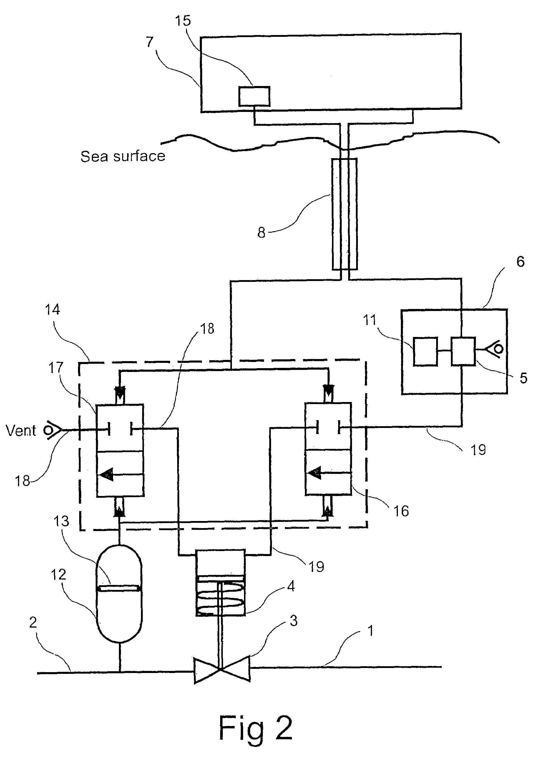
[0019]Referring now to FIG. 2, an embodiment of the present invention is shown as employed with a fluid extraction facility, in this instance a hydrocarbon extraction well. As in the previously described arrangement, a thin-walled section of pipeline 1 is connected to a thick-walled section of pipeline 2 via a hydraulically actuated valve comprising HIPPS valve 3 and failsafe hydraulic actuator 4. As before, a directional control valve 5 located in a sub-sea control module 6 is used to allow control of the HIPPS valve for purposes other than pressure protection, such as shutting down the production output. The hydraulic actuator 4 is fed hydraulic fluid, typically water-glycol rather than oil, via DCV 5 and umbilical 8 from hydraulic power unit 7, located above the sea surface. The pipeline 2 from the well tree is connected to a pressure transfer barrier 12. This device is shown in sectioned view, and comprises a sealed cylinder with a sliding piston 13 inside which is sealed to the...


PUM


Abstract

A protection system for a pipeline comprises a hydraulically actuated valve operable to switchably prevent a flow of fluid from a first section of the pipeline to a second section of the pipeline, a hydraulic fluid source for supplying hydraulic fluid to said hydraulically actuated valve to enable actuation thereof, a vent for venting hydraulic fluid from the hydraulically actuated valve, the hydraulically actuated valve being connected to the vent via a differential pressure valve to control venting of the hydraulically actuated valve, a pressure transfer barrier with a first port connected to the first section of the pipeline and a second port connected to said differential pressure valve, said differential pressure valve being supplied with hydraulic fluid at a reference pressure. If the pressure of fluid in the first section of pipeline exceeds the reference pressure of the hydraulic fluid supplied to the differential pressure valve, the differential pressure valve is caused to be in an open state, thereby causing the hydraulic pressure in the hydraulically actuated valve to be released via the vent. The protection system is of particular application to sub-sea hydrocarbon extraction wells.

Description

CROSS-REFERENCE TO RELATED APPLICATION[0001]This application claims the benefit of United Kingdom Patent Application No. 0309687.2, filed on Apr. 29, 2003, which hereby is incorporated by reference in its entirety.TECHNICAL FIELD OF THE INVENTION[0002]The present invention relates to a protection system for a pipeline, for example to safeguard production fluid pipelines in sub-sea fluid extraction wells, such as hydrocarbon extraction wells.BACKGROUND OF THE INVENTION[0003]Production fluid pipelines from wells are generally thin-walled in order to minimise the cost of the pipeline. Thus it is essential that they are protected against excessive pressure that might rupture the pipe, which would be very expensive to replace and cause environmental pollution. A conventional system used to protect pipelines from over-pressure is the high integrity pipeline protection system (HIPPS). Conventionally this is an electro-hydraulic system, employing pressure sensors to measure the pressure in ...

Claims


Application Information

Patent Timeline
IPC IPC(8): F16K31/12F16K17/02F16K31/122
CPCF16K31/1221F16K17/02E21B43/01Y10T137/777Y10T137/7762Y10T137/7761
Inventor WEBSTER, DAVID
Owner GE OIL & GAS UK LTD
Why Eureka
Try Eureka