Optical device for use under significantly varying ambient pressure

an optical device and ambient pressure technology, applied in special purpose vessels, waterborne vessels, underwater equipment, etc., can solve the problems of comparatively high cost of sealing, comparatively thick and consequently costly panes, heavy and large arrangement, etc., and achieve good and long-term reliable imaging properties.

Inactive Publication Date: 2006-05-16
CARL ZEISS OPTRONICS
View PDF8 Cites 0 Cited by
  • Summary
  • Abstract
  • Description
  • Claims
  • Application Information

AI Technical Summary

Benefits of technology

[0004]It is thus an object of the present invention to, at least to some extent, overcome the above disadvantages and to provide good and long term reliable imaging properties of an optical system used in an exposure process.
[0005]It is a further object of the present invention to provide an optical device having an improved optical performance of the entire system while simultaneously reducing the expenditure.
[0006]The present invention is based on the notion that an improved optical performance of the entire system can be achieved with a reduced expenditure by providing a protection apparatus that can be moved from a first functional position into a second functional position and is arranged outside the housing. In its first functional position, the protection apparatus covers and seals the first region relative to the environment of the housing in such a way that the pressure in an intermediate space between the protection apparatus and the first region is not higher than the first pressure level.
[0009]Due to these measures, the transparent element as well as the first sealing device only need to be designed for a comparatively low first pressure level, since they are protected from higher ambient pressures by the protection apparatus. This makes it possible to realize the transparent element, for example, a planar or convex pane or a lens, in a correspondingly thin fashion such that not only the material and the manufacturing costs for the transparent element are lowered, but the optical performance of the entire system is also improved because the absorption losses and aberrations are reduced due to the reduced thickness of the transparent element.
[0010]The optical device according to the invention may be advantageously utilized in all applications, in which the light only needs to be incident into the interior of the housing through the transparent element at comparatively low ambient pressures. This is the case, for example, with periscopes or optronics masts on submarines. Their optical functions, for example, a visual reconnaissance, usually are only required when their corresponding end is situated above the water level. The optical function is not required in the submerged state while the periscope or the optronics mast is retracted. This means that the transparent element can be covered by the protection apparatus without any negative effects in this state.

Problems solved by technology

Due to the high ambient pressures occurring in the submerged state, the expenditure for the seal is comparatively high and the panes themselves need to be realized in a comparatively thick and consequently costly fashion in order to withstand these high pressures.
This not only results in a comparatively expensive, heavy and large arrangement, but the required thickness of the panes also has negative effects on the optical performance of the entire system due to the associated absorption and the aberrations resulting thereof.
Anyway, this has the disadvantage that the periscope or optronics mast either must always be completely retracted at comparatively low submersion levels with low pressure levels or the components will have to be designed for higher pressure levels.

Method used


Image

  • Optical device for use under significantly varying ambient pressure
  • Optical device for use under significantly varying ambient pressure
  • Optical device for use under significantly varying ambient pressure

Examples


first embodiment

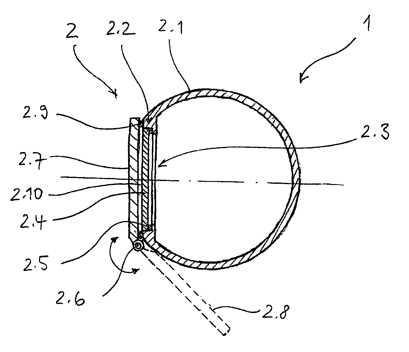
[0030]In the following, a first preferred embodiment of an optical device according to the invention will be described with reference to FIG. 1. FIG. 1 shows a schematic section through a periscope 1 of a submarine with a first preferred embodiment of the optical device 2 according to the invention arranged on the free end of the periscope 1.

[0031]The optical device 1 comprises a housing 2.1 with a first region 2.2 that contains a window-like recess 2.3. A transparent element in the form of a transparent pane 2.4 is inserted into this recess 2.3. Light can be incident into the interior of the housing 2.1 through the pane 2.4.

[0032]In the interior of the housing, the remainder of the optical system of the periscope 1—not illustrated in FIG. 1—is situated adjacent to the pane 2.4. This optical system needs to be protected from the admission of moisture.

[0033]A first sealing gap between the pane 2.4 and the housing 2.1 is sealed by means of a first sealing device in the form of a first...

second embodiment

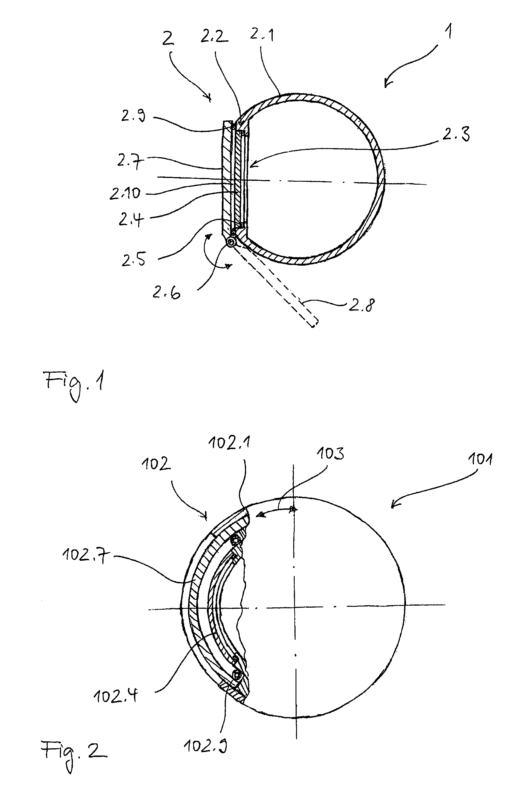
[0039]In the following, a second preferred embodiment of an optical device according to the invention will be described with reference to FIG. 2. FIG. 2 shows a schematic section through another preferred embodiment of a periscope 101 for a submarine, wherein another preferred embodiment of the optical device 102 according to the invention is arranged on the free end of the periscope 101. Since the basic function and design of this embodiment correspond to those of the embodiment shown in FIG. 1, only the respective differences between the two embodiments are discussed.

[0040]A first difference can be seen in the fact that the protection apparatus is realized in the form of a displaceable bulkhead 102.7 that is supported in the housing 102.1 and may be displaced in the direction of the double arrow 103, namely between the first functional position shown in which it covers the pane 102.4 and the second functional position—not shown—in which it leaves the pane 102.4 uncovered.

[0041]Ano...

third embodiment

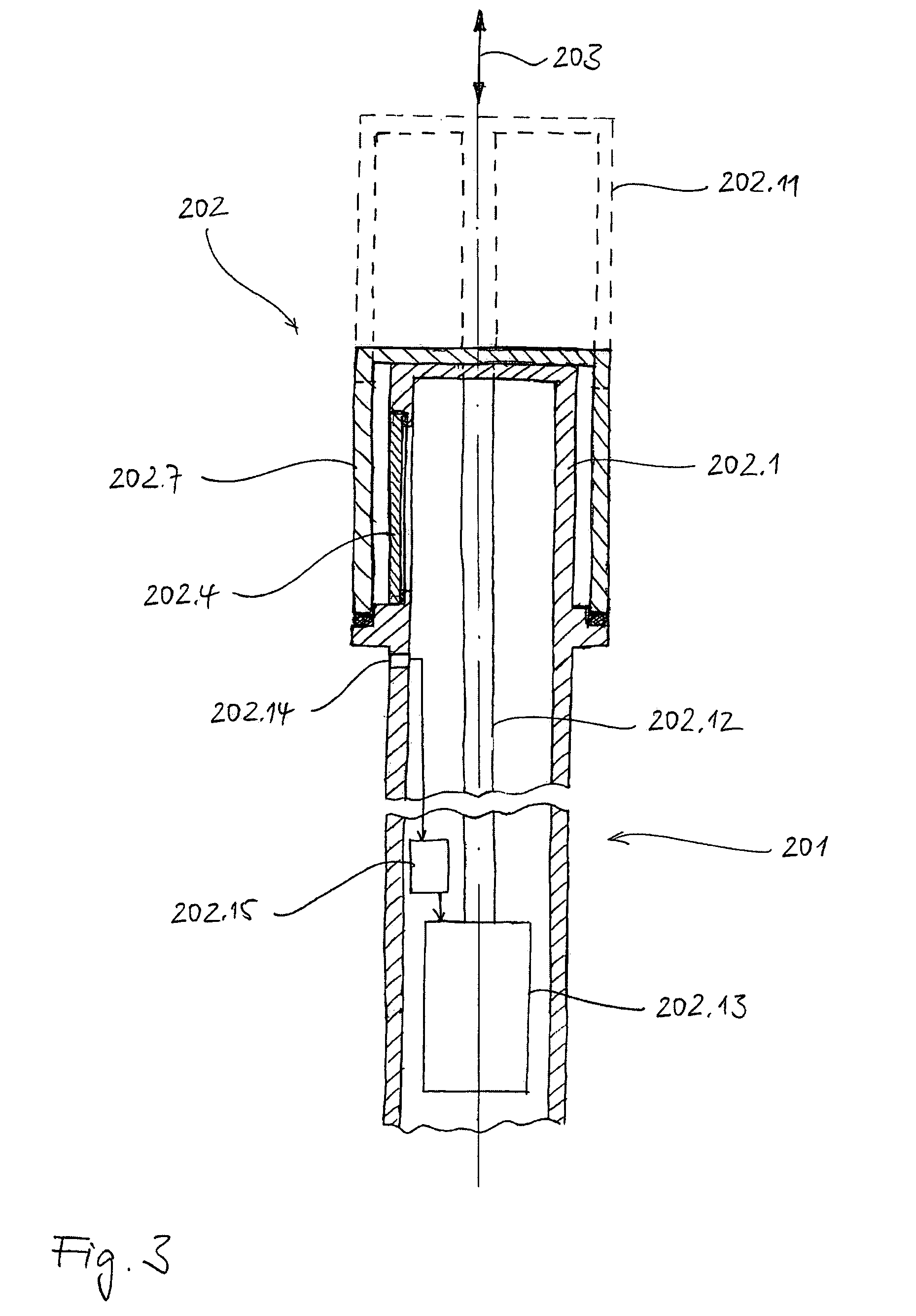
[0042]In the following, a third preferred embodiment of an optical device according to the invention will be described with reference to FIG. 3. FIG. 3 shows a schematic section through an optronics mast 201 for a submarine, wherein another preferred embodiment of the optical device 202 according to the invention is arranged on the free end of the optronics mast 201. Since the basic function and design of this embodiment also correspond to those of the embodiment shown in FIG. 1, only the respective differences between the two embodiments are discussed.

[0043]A first difference can be seen in the fact that the protection apparatus comprises a tubular casing in the form of a tubular cap 202.7 that surrounds the tubular housing 202.1 in the first functional position. The cap may be displaced in the direction of the double arrow 203, namely between the first functional position shown in which it covers the pane 202.4 and the second functional position that is indicated with broken lines...


PUM


Abstract

An optical device for use under significantly varying ambient pressure is provided comprising a housing, a transparent element, a first sealing device and a protection apparatus. The housing has an interior part, an environment outside the housing and a recess in a first region. The transparent element is arranged in the first region in a region of the recess. The first sealing device is sealing a first sealing gap between the transparent element and the housing. Furthermore, the first sealing device is sealing the interior part of the housing relative to the environment of the housing up to a first pressure level. The protection apparatus is arranged outside the housing and is displaceable from a first functional position into a second functional position. Furthermore, the protection apparatus, in the first functional position, covers the transparent element and seals the first region relative to the environment of the housing in such a way that a pressure in an intermediate space between the protection apparatus and the first region is not higher than the first pressure level if an ambient pressure in the environment of the housing exceeds the first pressure level. Finally, the protection apparatus, in the second functional position, leaves the transparent element uncovered.

Description

BACKGROUND OF THE INVENTION[0001]The present invention pertains to an optical device for use under significantly varying ambient pressure. The invention may be used in the context of a periscope or an optronics mast.[0002]In conventional periscopes or optronics masts for submarines, the panes, through which the light is incident, and the corresponding seal of the housing need to withstand the ambient pressure in any situation. Due to the high ambient pressures occurring in the submerged state, the expenditure for the seal is comparatively high and the panes themselves need to be realized in a comparatively thick and consequently costly fashion in order to withstand these high pressures. This not only results in a comparatively expensive, heavy and large arrangement, but the required thickness of the panes also has negative effects on the optical performance of the entire system due to the associated absorption and the aberrations resulting thereof.[0003]On the other hand, to deal wi...

Claims


Application Information

Patent Timeline
Patent Type & Authority Patents(United States)
IPC IPC(8): G02B5/12B63G8/38G02B23/08
CPCG02B23/08B63G8/38
Inventor WEISSER, DIRKTIETZ, TRAUGOTT
Owner CARL ZEISS OPTRONICS
Why Eureka
Try Eureka