Optical imaging arrangement with multiple metrology support units

a technology of optical imaging and support units, applied in the direction of optical apparatus testing, instruments, photomechanical equipment, etc., can solve the problems of not being able to use common refractive optics anymore, unable to achieve high-quality exposure, etc., to achieve good and long-term reliable imaging properties

Active Publication Date: 2018-05-22
CARL ZEISS SMT GMBH
View PDF29 Cites 2 Cited by
  • Summary
  • Abstract
  • Description
  • Claims
  • Application Information

AI Technical Summary

Benefits of technology

[0017]It is thus an object of the invention to, at least to some extent, overcome the above disadvantages and to provide good and long term reliable imaging properties of an optical imaging arrangement used in an exposure process.
[0018]It is a further object of the invention to reduce the effort necessary for an optical imaging arrangement while at least maintaining the imaging accuracy of the optical imaging arrangement used in an exposure process.
[0019]It is a further object of the invention to reduce the negative influence on imaging quality of residual low-frequency vibration disturbances introduced into the optical system of an optical imaging arrangement.
[0020]These objects are achieved according to the invention which, according to one aspect, is based on the technical teaching that an overall reduction of the effort necessary for an optical imaging arrangement while at least maintaining the imaging accuracy of the optical imaging arrangement even under the presence of low-frequency vibration disturbances may be achieved if the metrology support structure is split into a plurality of smaller separate substructures supporting subgroups of the metrology devices used in the imaging system. Such a split in separate smaller substructures has the great advantage that these substructures, due to their reduced size, may be more easily designed as components of increased rigidity and, hence, increased resonant frequency. Such increased rigidity and resonant frequencies lead to lower susceptibility of these support structures to low-frequency vibration disturbances, strongly reduced quasi-static deformation of the respective support structure and, ultimately, improved imaging accuracy.
[0021]It should be noted that, in many cases, it may be necessary to provide some additional metrology arrangement determining the spatial relation between the metrology device subgroups supported by the respective metrology support substructures in all degrees of freedom (DOF) in space which are relevant for the imaging quality in the specific imaging process performed (i.e. in at least one or more degrees of freedom, typically in all six degrees of freedom). However, this additional metrology effort is largely outweighed by the benefit achieved due to the strongly reduced quasi-static deformation of the respective support substructure and its clear benefits in terms of imaging accuracy as well as the relaxation of the requirements regarding eventual vibration isolated support of the respective substructures.

Problems solved by technology

In this EUV range it is not possible to use common refractive optics any more.
This is due to the fact that, in this EUV range, the materials commonly used for refractive optical elements show a degree of absorption that is too high for obtaining high quality exposure results.
The transition to the use of high numerical aperture (e.g. NA>0.4 to 0.5) reflective systems in the EUV range leads to considerable challenges with respect to the design of the optical imaging arrangement.
Among others, the above leads to very strict requirements with respect to the relative position between the components participating in the exposure process.
On the other hand, an increase in the numerical aperture, typically, leads to an increased size of the optical elements used, also referred to as the optical footprint of the optical elements.
The increased optical footprint of the optical elements used has a negative impact on their dynamic properties and the control system used to achieve the above adjustments.
Furthermore, the increased optical footprint typically leads to larger light ray incidence angles.
However, at such increased light ray incidence angles transmissivity of the multi-layer coatings typically used for generating the reflective surface of the optical elements is drastically reduced, obviously leading to an undesired loss in light power and an increased heating of the optical elements due to absorption.
One problem arising from the above situation is that such large structures are generally less rigid.
Such less rigid support structures not only contribute to further restrictions of adjustment control performance, but also to residual errors due to quasi-static deformations of the respective structure caused by residual low frequency vibration disturbances.
However, there are clear practical limits to such an approach.
A crucial limitation is that methods for manufacturing such large structures from suitable materials required to achieve appropriate dynamic and thermal properties in such a high precision imaging arrangement are not readily available.
A further limitation in the ability to actively handle such residual low frequency vibration disturbances lies in the difficulties to practically capture such residual low-frequency accelerations at sufficient accuracy avoiding the negative effects of drift and noise, respectively.

Method used


Image

  • Optical imaging arrangement with multiple metrology support units
  • Optical imaging arrangement with multiple metrology support units
  • Optical imaging arrangement with multiple metrology support units

Examples


first embodiment

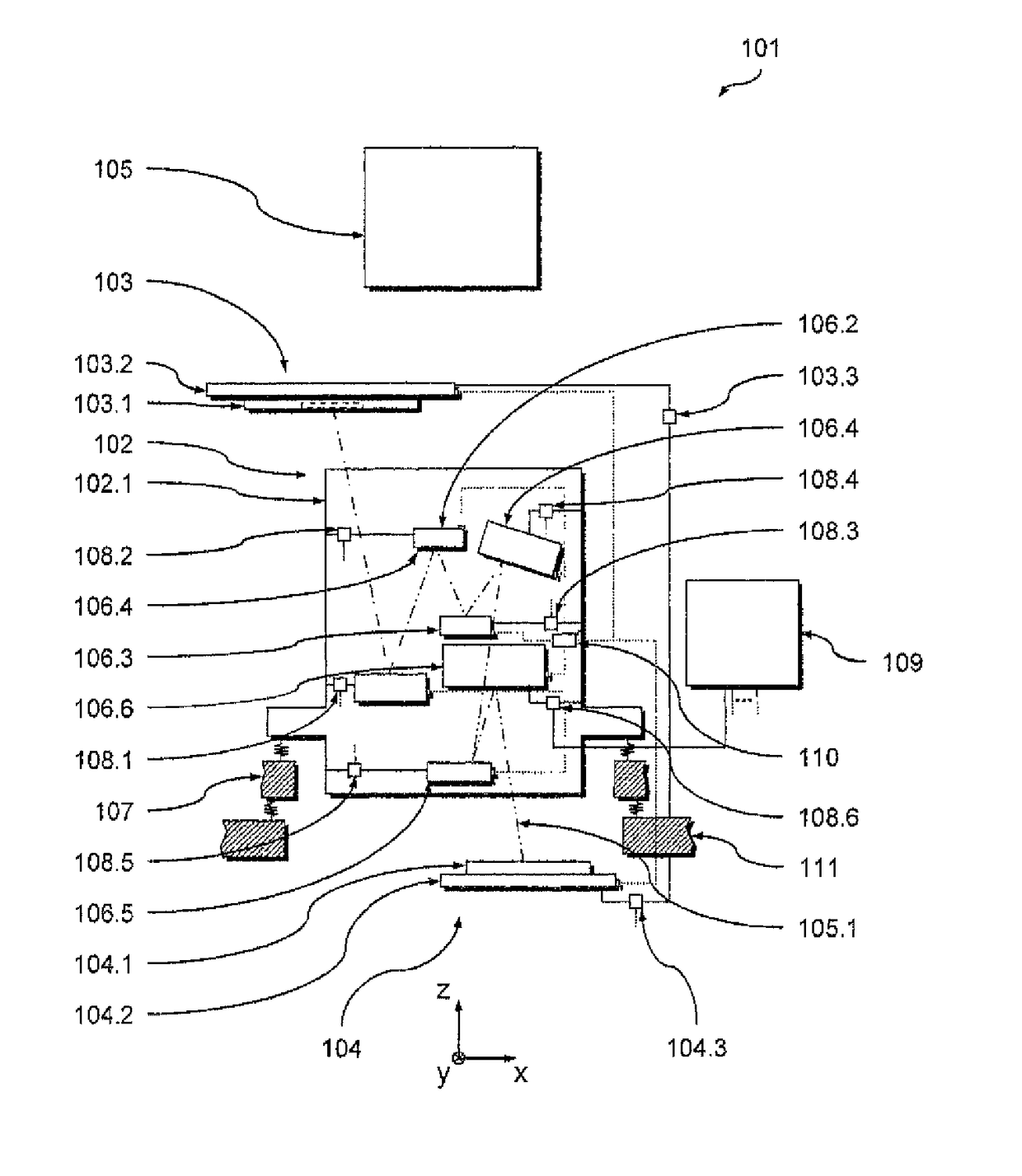
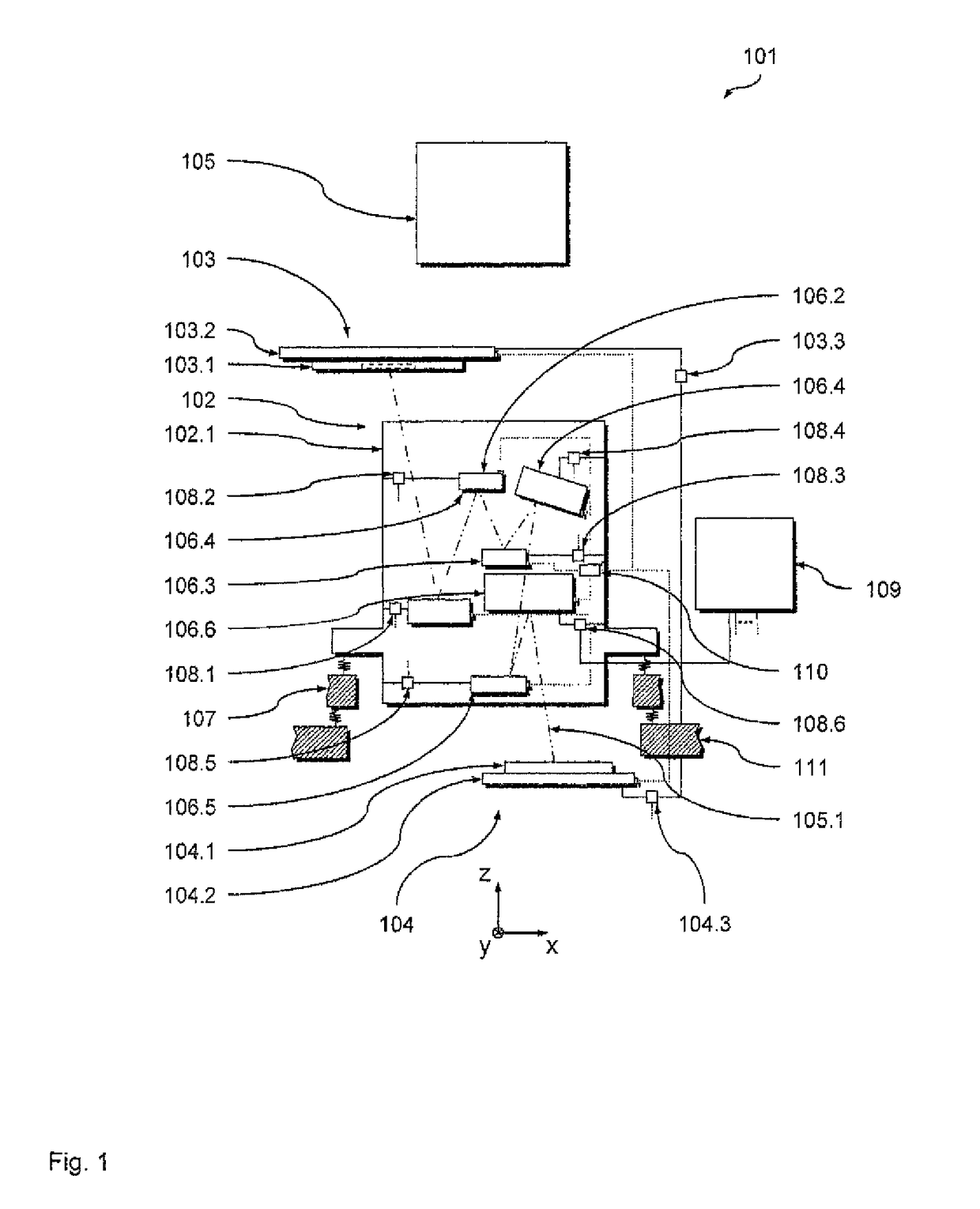
[0037]In the following, a preferred first embodiment of an optical imaging arrangement 101 according to the invention with which preferred embodiments of methods according to the invention may be executed will be described with reference to FIGS. 1 to 5. To facilitate understanding of the following explanations a xyz coordinate system is introduced in the Figures, wherein the z-direction designates the vertical direction (i.e. the direction of gravity).

[0038]FIG. 1 is a highly schematic and not-to-scale representation of the optical imaging arrangement in the form of an optical exposure apparatus 101 operating in the EUV range at a wavelength of 13 nm. The optical exposure apparatus 101 comprises an optical projection unit 102 adapted to transfer an image of a pattern formed on a mask 103.1 (located on a mask table 103.2 of a mask unit 103) onto a substrate 104.1 (located on a substrate table 104.2 of a substrate unit 104). To this end, the optical exposure apparatus 101 comprises a...

second embodiment

[0126]In the following, a second preferred embodiment of an imaging arrangement 201 according to the invention with which preferred embodiments of the methods according to the invention may be executed will be described with reference to FIGS. 6 and 7. The optical imaging arrangement 201 in its basic design and functionality largely corresponds to the optical imaging arrangement 101 such that it is here mainly referred to the differences. In particular, identical components have been given the identical reference, while like components are given the same reference numeral increased by the value 100. Unless explicitly deviating statements are given in the following, explicit reference is made to be explanations given above in the context of the first embodiment with respect to these components.

[0127]The only difference between the optical imaging arrangement 201 and the optical imaging arrangement 101 lies within the deviating concept of using the reference metrology device 210.9 of ...

third embodiment

[0141]In the following, a third preferred embodiment of an optical imaging arrangement 301 according to the invention with which preferred embodiments of the methods according to the invention may be executed will be described with reference to FIG. 8. The optical imaging arrangement 301 in its basic design and functionality largely corresponds to the optical imaging arrangement 201 such that it is here mainly referred to the differences. In particular, identical components have been given the identical reference, while like components are given the same reference numeral increased by the value 100. Unless explicitly deviating statements are given in the following, explicit reference is made to be explanations given above in the context of the second embodiment with respect to these components.

[0142]The main difference between the optical imaging arrangement 201 and the optical imaging arrangement 301 lies within the deviating split design of the projection system metrology support ...


PUM

PropertyMeasurementUnit
resonant frequencyaaaaaaaaaa

Abstract

An optical imaging arrangement includes an optical projection system and a support structure system. The optical projection system includes a group of optical elements configured to transfer, in an exposure process using exposure light along an exposure light path, an image of a pattern of a mask onto a substrate. The support structure system includes an optical element support structure and a metrology support structure. The optical element support structure supports the group of optical elements, while the metrology support structure supports a group of metrology devices associated with the group of optical elements and configured to capture status information representative of at least one of a position and an orientation of each of the optical elements in at least one degree of freedom up to all six degrees of freedom.

Description

CROSS-REFERENCE TO RELATED APPLICATIONS[0001]The present application is a continuation of, and claims benefit under 35 USC 120 to, international application PCT / EP2012 / 060284, filed May 31, 2012, the entire disclosure of which is incorporated by reference herein.BACKGROUND OF THE INVENTION[0002]The invention relates to optical imaging arrangements used in exposure processes, in particular to optical imaging arrangements of microlithography systems. It further relates to a method of supporting components of an optical projection unit. The invention may be used in the context of photolithography processes for fabricating microelectronic devices, in particular semiconductor devices, or in the context of fabricating devices, such as masks or reticles, used during such photolithography processes.[0003]Typically, the optical systems used in the context of fabricating microelectronic devices such as semiconductor devices comprise a plurality of optical element units comprising optical elem...

Claims


Application Information

Patent Timeline
Patent Type & Authority Patents(United States)
IPC IPC(8): G01B11/14G01M11/08G03F7/20
CPCG01M11/081G01B11/14G03F7/70833G03F7/70316G03F7/70825G03F7/709
Inventor KWAN, YIM-BUN PATRICKRUINEMANS, ERIK
Owner CARL ZEISS SMT GMBH
Why Eureka
Try Eureka