Optical element unit for exposure processes

a technology of optical elements and exposure processes, applied in the field of optical element units for exposure processes, can solve the problems of undesirable adverse effects on the useful life of the glue seal, and degradation of the optical performance of the optical system, and achieve good and long-term reliable imaging properties of the optical system

Inactive Publication Date: 2009-06-09
CARL ZEISS SMT GMBH
View PDF3 Cites 0 Cited by
  • Summary
  • Abstract
  • Description
  • Claims
  • Application Information

AI Technical Summary

Benefits of technology

[0014]It is thus an object of the present invention to, at least to some extent, overcome the above disadvantages and to provide good and long term reliable imaging properties of an optical system, in particular of an optical system used in an immersion exposure process.
[0015]It is a further object of the present invention to easily and reliably prevent intrusion of contaminants into the inner part of an optical element unit in order to maximize the useful life without maintenance of the optical system within an optical element unit, in particular an optical element unit used in an immersion exposure process.
[0016]It is a further object of the present invention to hold the optical element separating the inner part of an optical element unit from an outer environment in a simple and deformation minimized manner in order to provide good and reliable imaging properties of the optical system, in particular of an optical system used in an immersion exposure process.

Problems solved by technology

This immersion of the last optical element causes several problems.
One problem lies within the fact that the rest of the optical system usually has to be protected against any contact with the immersion medium, fractions thereof or reaction products thereof to avoid contamination of the optical elements with such contaminants.
Such contaminants would otherwise lead to an undesirable degradation of the optical performance of the optical system.
These varying stresses, of course, may have adverse effects on the useful life of the glue seal.
Furthermore, the glue itself may be a source of contaminants leading to a contamination of the optical elements and, consequently, to an undesirable degradation of the optical performance of the optical system.
A further problem lies within the deformation of the last lens element due to different coefficients of thermal expansion of the last optical element and the housing.
Anyway, such a housing would be rather expensive.
The problem of the intrusion of parts of the external atmosphere into the interior of the housing of the optical system used in the exposure process does not only exist for optical exposure systems using immersion techniques.
This solution, on the one hand, has the disadvantage that, due to the drawing off process in the gap, the pressure within the housing may drop considerably leading to an unwanted deformation of the ultimate optical elements.
A further disadvantage lies within the fact that the gap width is defined by the fixed dimensions of the posts such that an adjustment of the gap width is not possible.
Furthermore, again, the differences in the coefficient of thermal expansion between the ultimate optical element lead to the introduction of deformations into the ultimate optical element clamped between the housing and the clamping ring.

Method used


Image

  • Optical element unit for exposure processes
  • Optical element unit for exposure processes
  • Optical element unit for exposure processes

Examples


first embodiment

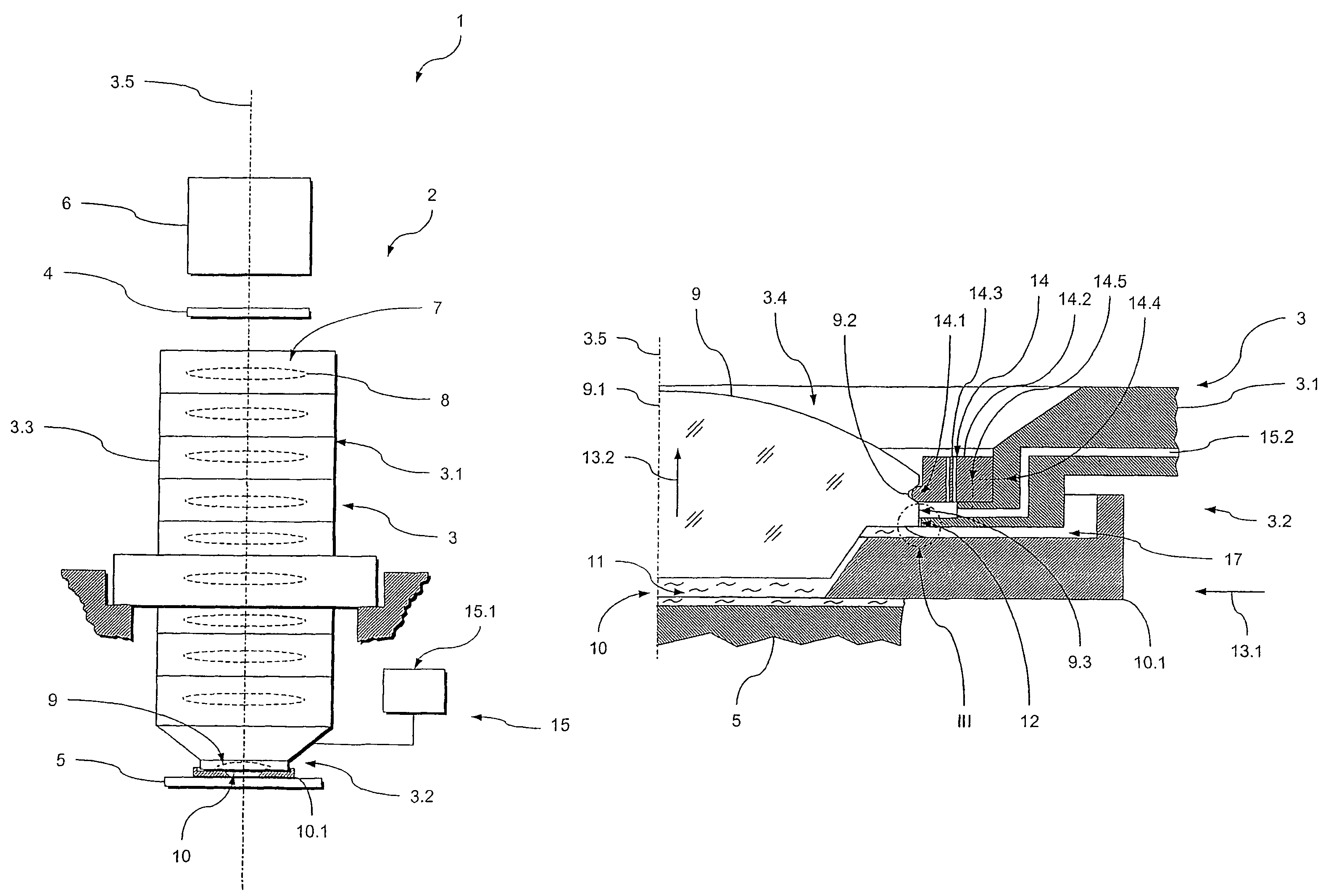
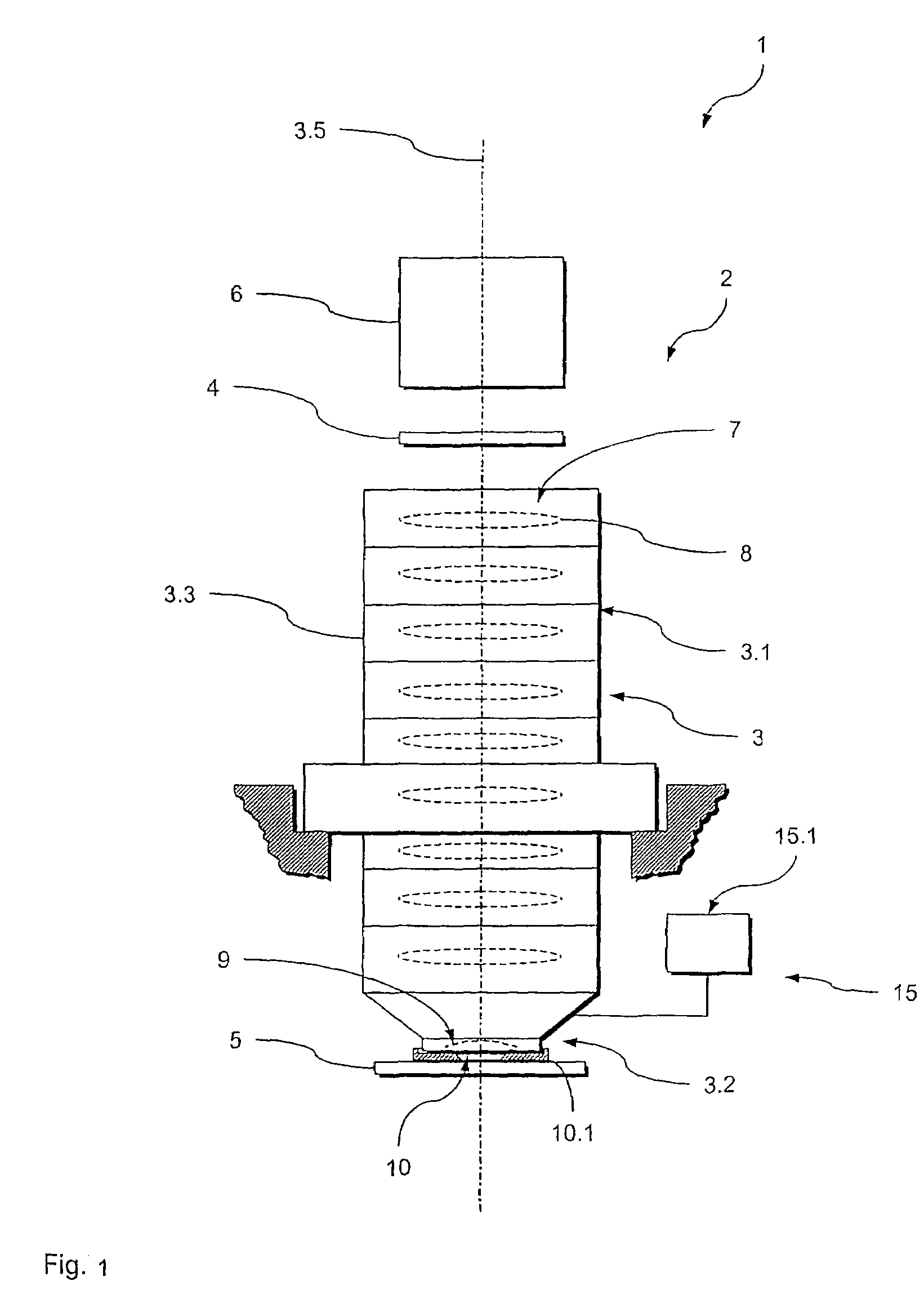
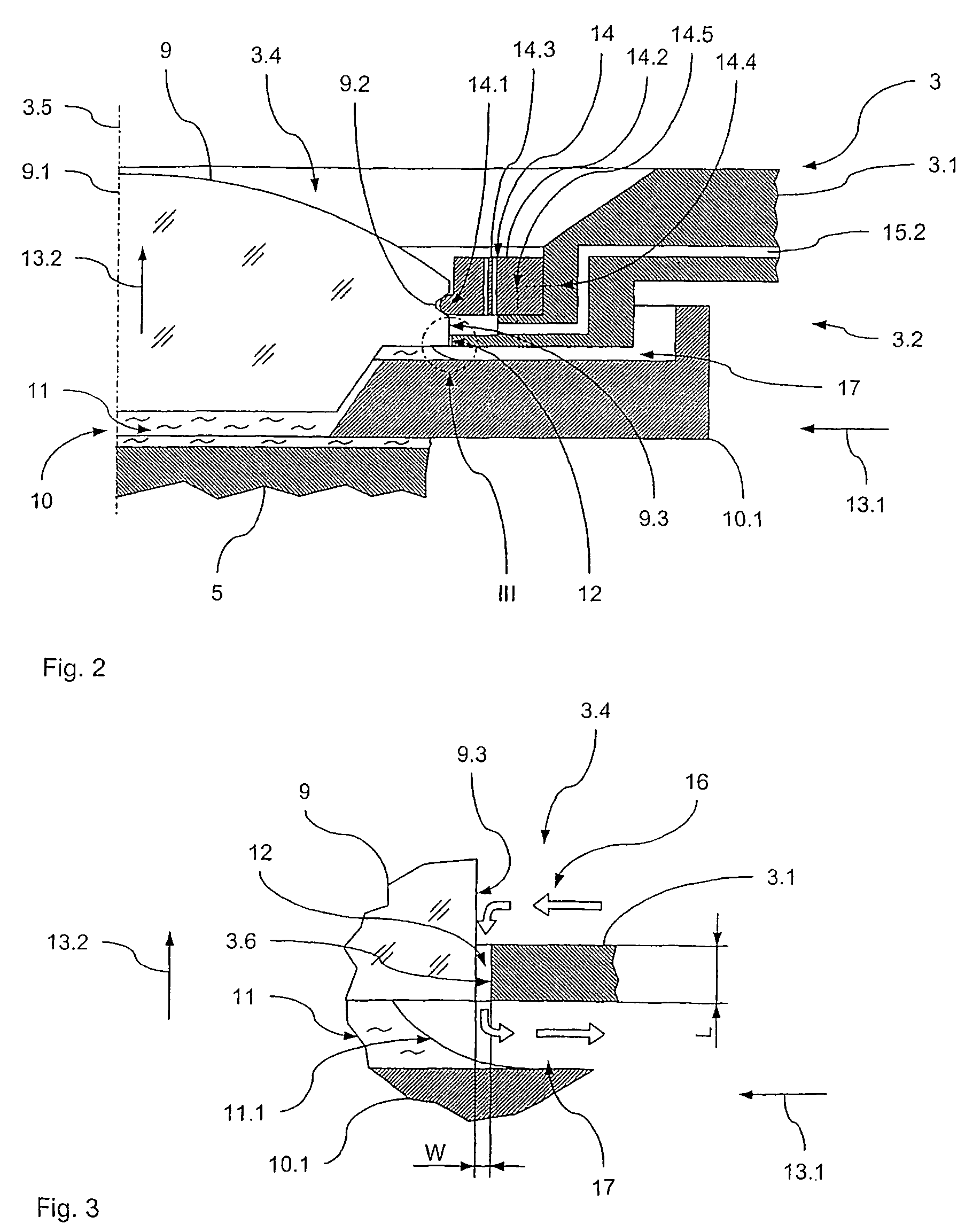
[0041]In the following, a first preferred embodiment of an optical exposure apparatus 1 according to the present invention comprising an optical projection system 2 with an optical element unit 3 according to the present invention will be described with reference to FIGS. 1 to 3.

[0042]The optical exposure apparatus 1 is adapted to transfer an image of a pattern formed on a mask 4 onto a substrate 5. To this end, the optical exposure apparatus 1 comprises an illumination system 6 illuminating said mask 4 and the optical element unit 3. The optical element unit 3 projects the image of the pattern formed on the mask 4 onto the substrate 5, e.g. a wafer or the like.

[0043]To this end, the optical element unit 3 holds an optical element group 7. This optical element group 7 is held within a housing 3.1 of the optical element unit 3. The optical element group 7 comprises a number of optical elements 8, such as lenses, mirrors or the like, and an ultimate optical element in the form of a la...

second embodiment

[0071]In the following, a second preferred embodiment of an optical exposure apparatus 101 according to the present invention comprising an optical projection system 102 with an optical element unit 103 according to the present invention will be described with reference to FIGS. 4 and 5.

[0072]The optical exposure apparatus 101 is adapted to transfer an image of a pattern formed on a mask 104 onto a substrate 105. To this end, the optical exposure apparatus 101 comprises an illumination system 106 illuminating said mask 104 and the optical element unit 103. The optical element unit 103 projects the image of the pattern formed on the mask 104 onto the substrate 105, e.g. a wafer or the like.

[0073]To this end, the optical element unit 103 holds an optical element group 107. This optical element group 107 is held within a housing 103.1 of the optical element unit 103. The optical element group 107 comprises a number of optical elements 108, such as lenses, mirrors or the like, and a las...

third embodiment

[0095]In the following, a third preferred embodiment of an optical exposure apparatus 201 according to the present invention comprising an optical projection system 202 with an optical element unit 203 according to the present invention will be described with reference to FIGS. 6 and 7.

[0096]The optical exposure apparatus 201 is adapted to transfer an image of a pattern formed on a mask 204 onto a substrate 205. To this end, the optical exposure apparatus 201 comprises an illumination system 206 illuminating said mask 204 and the optical element unit 203. The optical element unit 203 projects the image of the pattern formed on the mask 204 onto the substrate 205, e.g. a wafer or the like.

[0097]To this end, the optical element unit 203 holds an optical element group 207. This optical element group 207 is held within a housing 203.1 of the optical element unit 203. The optical element group 207 comprises a number of optical elements 208, such as lenses, mirrors or the like, and a last...


PUM

PropertyMeasurementUnit
gap widthaaaaaaaaaa
gap lengthaaaaaaaaaa
sealing gap widthaaaaaaaaaa

Abstract

An optical element unit is provided comprising an optical element group; a housing receiving said optical element group and having an inner housing part and an exit end; and a purge unit connected to said housing and providing a purge medium to said inner housing part. The optical element group comprises an ultimate optical element. The ultimate optical element is located at the exit end of housing and separates the inner housing part from an environment external to the housing. The ultimate optical element and the housing define a sealing gap. The purge unit provides purge medium to the sealing gap to prevent intrusion of contaminants into the inner housing part.

Description

BACKGROUND OF THE INVENTION[0001]The present invention relates to optical element units for exposure processes, in particular exposure processes using immersion techniques, and, in particular, to optical element units of microlithography systems using immersion techniques. It also relates to optical exposure apparatuses comprising such an optical element unit. Furthermore, it relates to a method of preventing intrusion of contaminants into an optical element unit as well as a method of holding an ultimate optical element of an optical element unit. The invention may be used in the context of photolithography processes for fabricating microelectronic devices, in particular semiconductor devices, or in the context of fabricating devices, such as masks or reticles, used during such photolithography processes.[0002]Typically, the optical systems used in the context of fabricating microelectronic devices such as semiconductor devices comprise a plurality of optical elements, such as lens...

Claims


Application Information

Patent Timeline
Patent Type & Authority Patents(United States)
IPC IPC(8): G03B27/54G03F7/20
CPCG02B7/023G03B27/52G03F7/70341G03F7/70933G02B27/0006G03F7/70808G03F7/70833G02B1/18
Inventor GELLRICH, BERNHARDKUGLER, JENSSCHLETTERER, THOMASLIMBACH, GUIDOKALLER, JULIANSCHERLE, HANS-JUERGENMUELLER, DETLEVSCHMEREK, DIETER
Owner CARL ZEISS SMT GMBH
Why Eureka
Try Eureka