Cartridge type applicator

a cartridge type and applicator technology, applied in the field of cartridge type applicators, can solve the problems of application failure, unusable cartridge type applicator, and limited usable viscosity of cartridge type applicator, and achieve the effect of high viscosity application liquid

Inactive Publication Date: 2006-05-16
MITSUBISHI PENCIL CO LTD
View PDF12 Cites 12 Cited by
  • Summary
  • Abstract
  • Description
  • Claims
  • Application Information

AI Technical Summary

Benefits of technology

[0010]The present invention has been devised in order to solve the above problems, it is therefore an object of the present invention to provide a cartridge type applicator which can prevent the application liquid from flowing back from the applying portion into the cartridge and which is suitable for use with a high viscosity application liquid.

Problems solved by technology

With this conventional applicator 70 thus configured, the pressure in cartridge 80 decreases due to repeated liquid discharge, hence the liquid at the applying portion is drawn back into the cartridge, causing application failure.
In some cases, the applicator may become unusable for sanitary reasons.
Further, this kind of cartridge type applicator has a usable viscosity limit with respect to the application liquid, suffering problems with high viscosity liquids, through no problems occur with low viscosity liquids.

Method used


Image

  • Cartridge type applicator
  • Cartridge type applicator
  • Cartridge type applicator

Examples


Embodiment Construction

[0053]The preferred embodiments of cartridge type applicators of the present invention will hereinbelow be detailed with reference to the accompanying drawings. It should be noted that the applicator according to the present invention is not limited to the following embodiments.

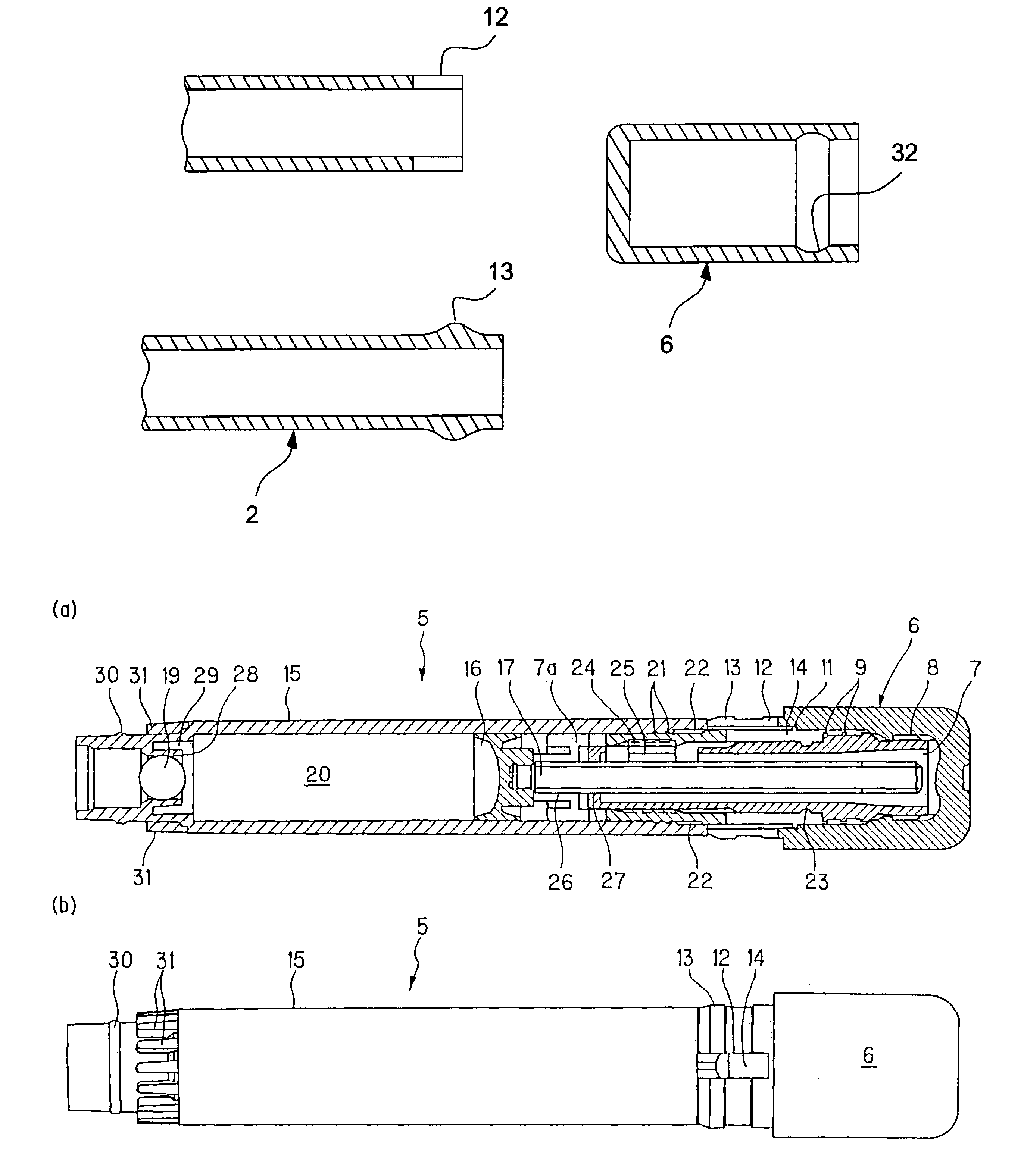
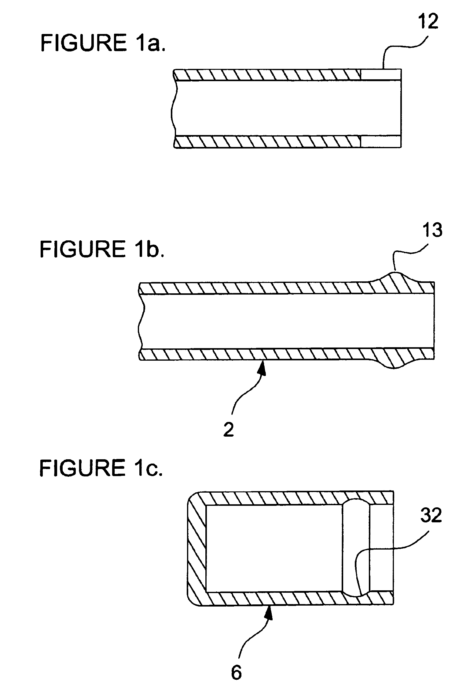
[0054]One embodiment of an applicator of the present invention is a cartridge type writing instrument 1 shown in FIG. 1. Writing instrument 1 is mainly composed of an approximately cylindrical barrel 2, a front barrel 3 having a writing part (applying portion) 4 arranged at the front end of barrel 2, a cartridge tank 5 detachably inserted into barrel 2, and a tail plug 6.

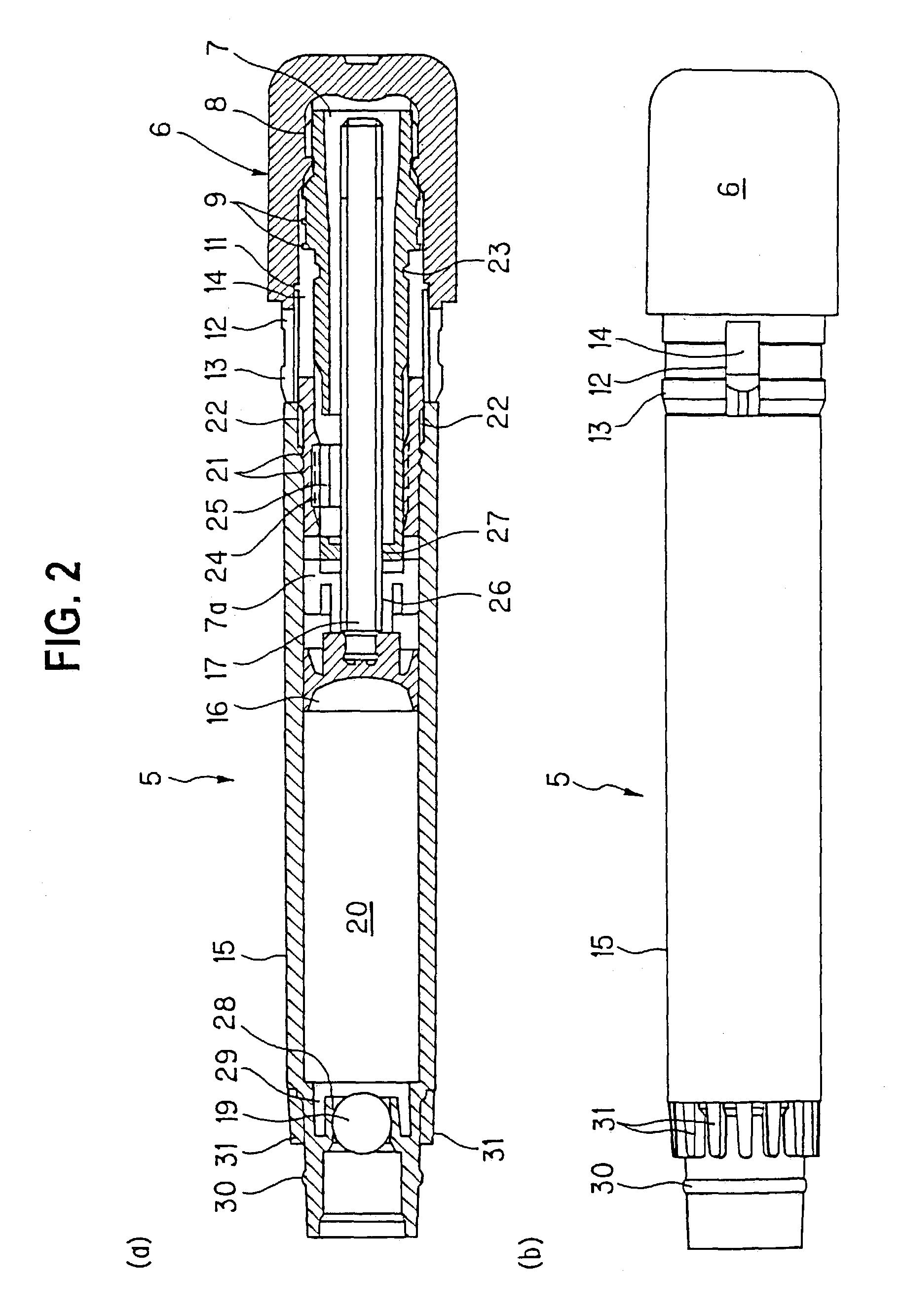
[0055]Cartridge tank 5 shown in FIGS. 1 to 3 is inserted in and fitted to barrel 2 and removed therefrom. This means that the cartridge tank is replaceable with respect to writing instrument 1. Therefore, cartridge tank 5 is covered with an unillustrated protecting cap or the like, and sold separately on the market.

[0056]As shown in FIG. 2, a...


PUM


Abstract

The object of the present invention is to provide a cartridge type applicator which can prevent the application liquid from flowing back from the applying portion into the cartridge and which is suitable for use with a high viscosity application liquid. This applicator includes an advancing mechanism or piston mechanism made up of a sealing plug disposed inside a cylindrical cartridge tank for constituting the rear end wall of the tank, and a rod member attached to the sealing plug for causing the sealing plug to move in the axial direction of the tank; and an actuator (actuating member) for causing the rod member to move or advance in the axial direction by rotation thereof, and is constructed such that, when the actuator is turned, the rod member causes the sealing plug to move in the axial direction so as to reduce the volume of the space inside the tank.

Description

BACKGROUND OF THE INVENTION[0001](1) Field of the Invention[0002]The present invention relates to an applicator of a pen (brush) type for application (including writing and drawing) of ink, cosmetics such as manicure and the like and other application liquids, more detailedly relating to a cartridge type applicator having a cylindrical cartridge tank which stores application liquid and can supply the application liquid to the applying portion such as a writing tip or the like.[0003](2) Description of the Prior Art[0004]As a conventional applicator, there has been a proposal of a cartridge type writing instrument shown in FIGS. 14 and 15 (see, for example, the publication of Japanese Registered Utility Model No. 2602464). This cartridge type applicator is constructed of an applicator body 70, a cartridge tank 80 and a tail plug 90.[0005]Applicator body 70 is made of synthetic resin, having an opening at the rear end and a front barrel 71 integrally formed at the front end, with an an...

Claims


Application Information

Patent Timeline
Patent Type & Authority Patents(United States)
IPC IPC(8): B43K5/00B43K23/08A45D29/18A45D34/04B05C17/00B43K5/06B43K8/02
CPCB43K5/06
Inventor ENDOU, MITSURU
Owner MITSUBISHI PENCIL CO LTD
Why Eureka
Try Eureka