Electrical connector with seating indicator

a technology of electrical connectors and indicators, applied in the direction of coupling bases/cases, coupling device connections, incorrect coupling prevention, etc., can solve the problems of increasing manufacturing time and cost, and achieve the effect of reducing manufacturing costs and facilitating connections

Inactive Publication Date: 2006-05-16
HUBBELL INC
View PDF7 Cites 60 Cited by
  • Summary
  • Abstract
  • Description
  • Claims
  • Application Information

AI Technical Summary

Benefits of technology

[0007]Yet another object of the present invention is to provide an electrical connector with a seating indicator that is easier and less expensive to manufacture.

Problems solved by technology

Also, these conventional electrical connectors require the manufacture of ring in addition to the electrical connector, thereby increasing manufacturing time and costs.

Method used


Image

  • Electrical connector with seating indicator
  • Electrical connector with seating indicator
  • Electrical connector with seating indicator

Examples


Embodiment Construction

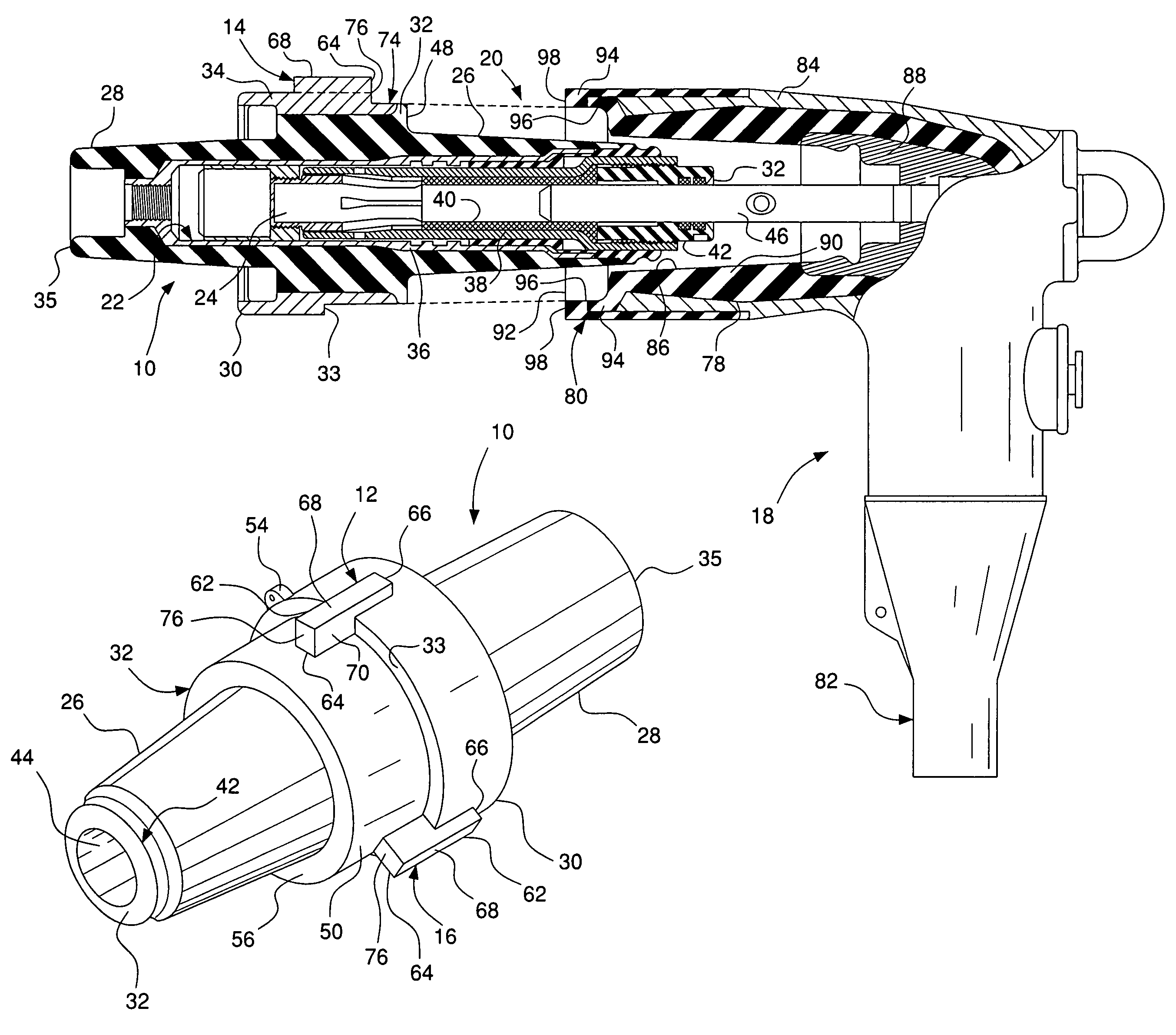
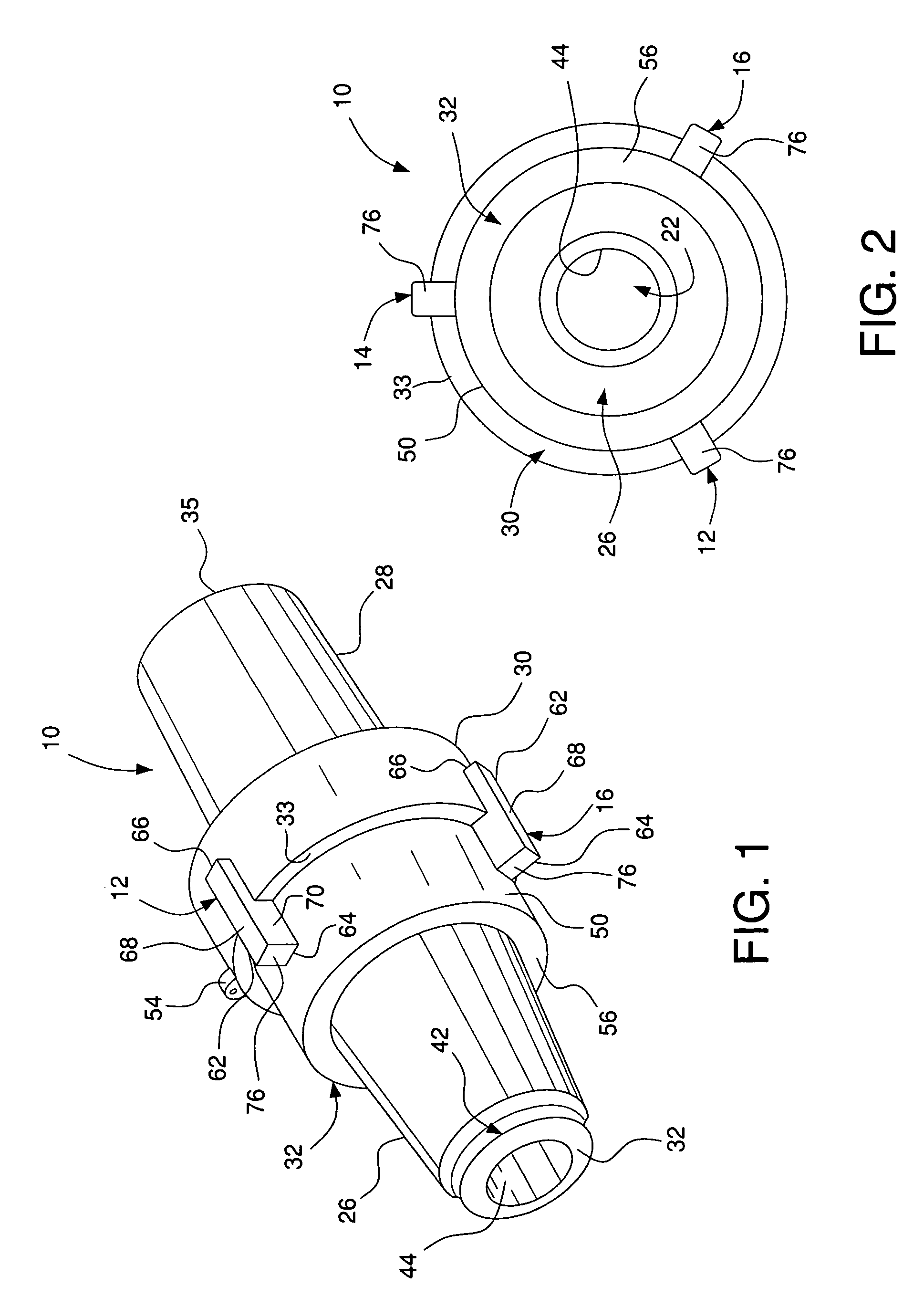
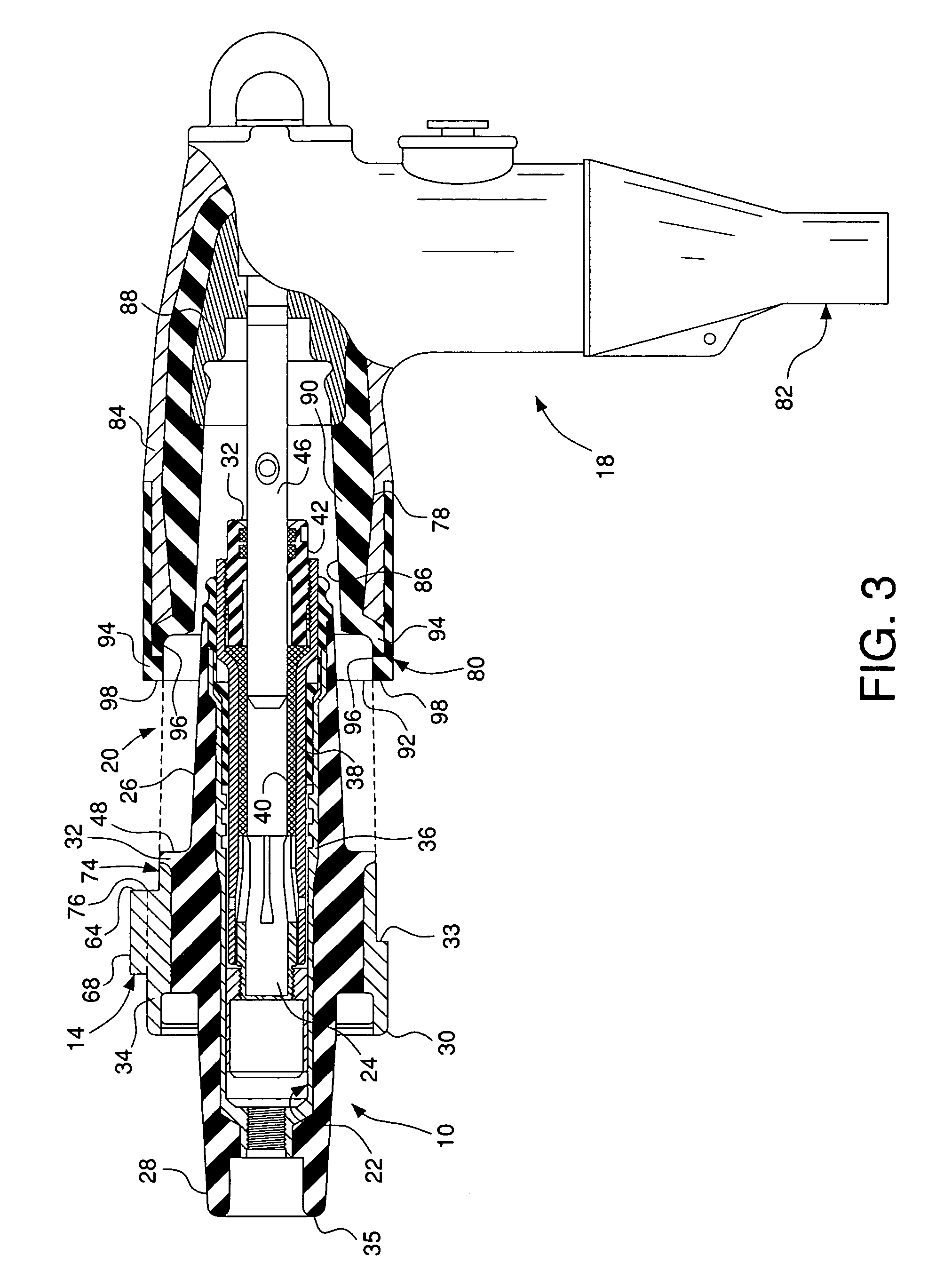
[0018]Referring to FIGS. 1–4, an electrical connector 10 in accordance with the present invention includes a plurality of radially extending indicator ribs 12, 14 and 16 which provide a visual indication of proper mating of a first electrical connector 10 with a second electrical connector 18. Upon connection, electrical connector 10 and electrical connector 18 form an electrical connector assembly 20 and the minimum distance, that is little or no space, between indicators ribs 12, 14 and 16 of connector 10 and the second electrical connector 18, indicating proper mating.

[0019]Electrical connector 10 can be any type of electrical connector adapted to be mated with a second electrical connector. For example, electrical connector can be a high voltage bushing insert that mates with a high voltage elbow cable connector. The general structure of a bushing insert and a cable connector are disclosed in commonly owned U.S. Pat. No. 6,213,799 to Jazowski et al.

[0020]Electrical connector 10 ...


PUM


Abstract

An electrical connector includes a body with first and second end sections, a mid-section disposed between the first and second end sections. The mid-section is radially larger than each of the first and second end sections and includes an outer surface. A transition shoulder is disposed between the first end section and the mid-section. The transition shoulder includes a face wall extending between the outer surface of the mid-section and an outer surface of the first end section. A plurality of radial indicator ribs extend from the outer surface of the mid-section. Each of the radial indicator ribs includes an abutment surface laterally offset from the face wall of the transition shoulder to abut or almost abut a portion of a mating electrical connector.

Description

FIELD OF THE INVENTION[0001]The present invention generally relates to an electrical connector with a seating indicator for indicating proper connection with a mating electrical connector. More specifically, the electrical connector includes a plurality of radial ribs that abut the mating electrical connector, thereby providing a visual indication of proper mating between the two connectors.BACKGROUND OF THE INVENTION[0002]Conventional mating electrical connectors employ a ring or band disposed on one of the connectors to provide a visual indication of proper connection between the two mating electrical connectors. The ring is typically either molded into the connector or formed separately and slid onto the connector. For example, U.S. Pat. No. 6,213,799 to Jazowski, the subject matter of which is herein incorporated by reference, discloses a bushing insert 10 and mating elbow connector 12 with a ring 100 disposed on a shoulder 22 of bushing insert 10. Ring 100 is brightly colored a...

Claims


Application Information

Patent Timeline
Patent Type & Authority Patents(United States)
IPC IPC(8): H01R3/00H01R13/641
CPCH01R13/641H01R13/53Y10S439/921
Inventor ZHAO, TIEBINWANG, JEFFERSONCAMERON, JAMES F.
Owner HUBBELL INC
Why Eureka
Try Eureka