Belt-type continuously variable transmission

Inactive Publication Date: 2006-05-16
JATCO LTD
View PDF9 Cites 2 Cited by
  • Summary
  • Abstract
  • Description
  • Claims
  • Application Information

AI Technical Summary

Benefits of technology

[0004]As disclosed in Japanese patent No. H7-92124, issued Oct. 9, 1995, an offset dX between a median plane of a groove in a drive pulley and a median plane of a groove in a driven pulley (in other words, an amount of misalignment) is set at zero when the gear ratio is on the top side. Hence when the gear rat

Problems solved by technology

As a result, durability may decrease due to

Method used


Image

  • Belt-type continuously variable transmission
  • Belt-type continuously variable transmission
  • Belt-type continuously variable transmission

Examples


Embodiment Construction

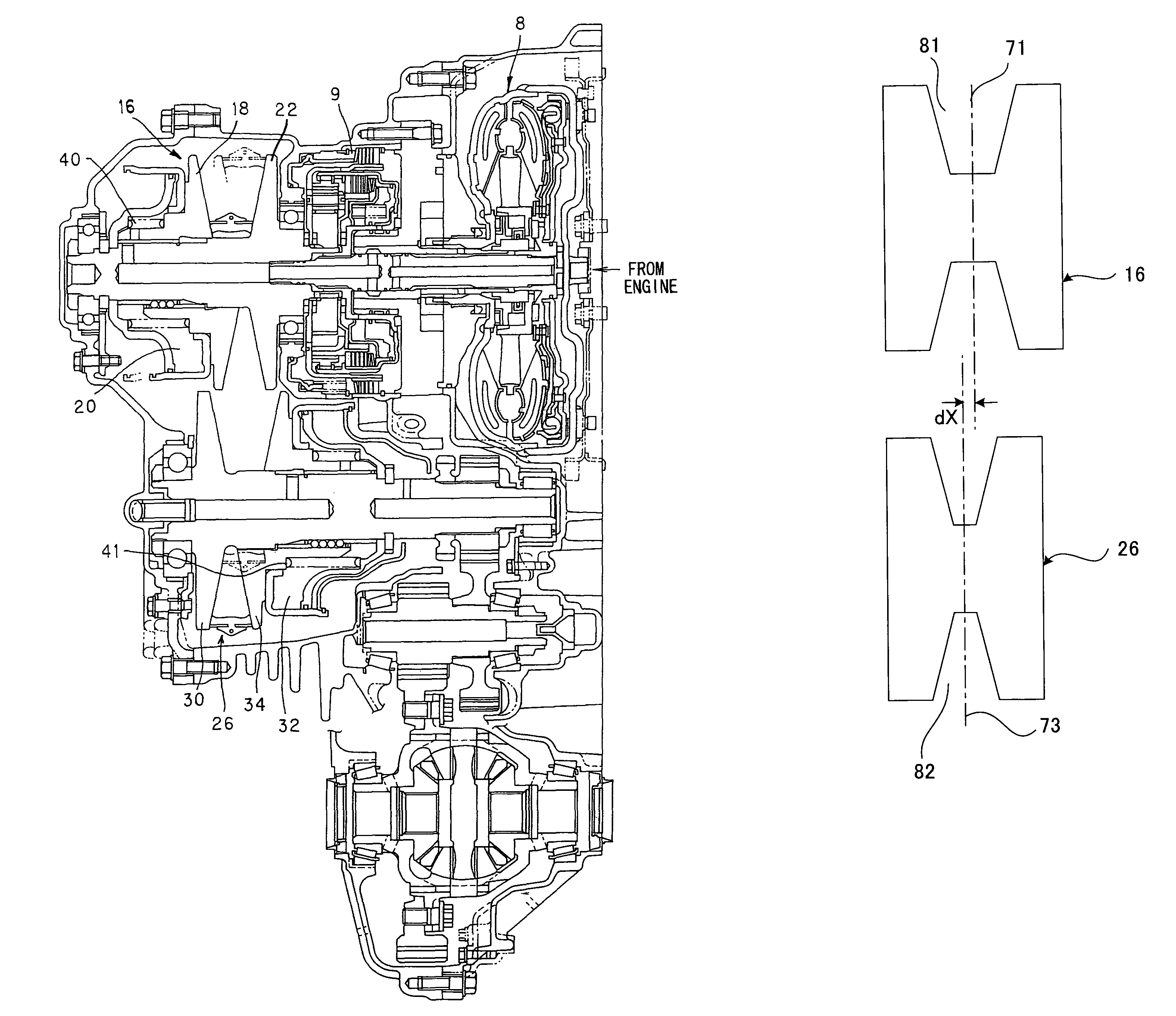
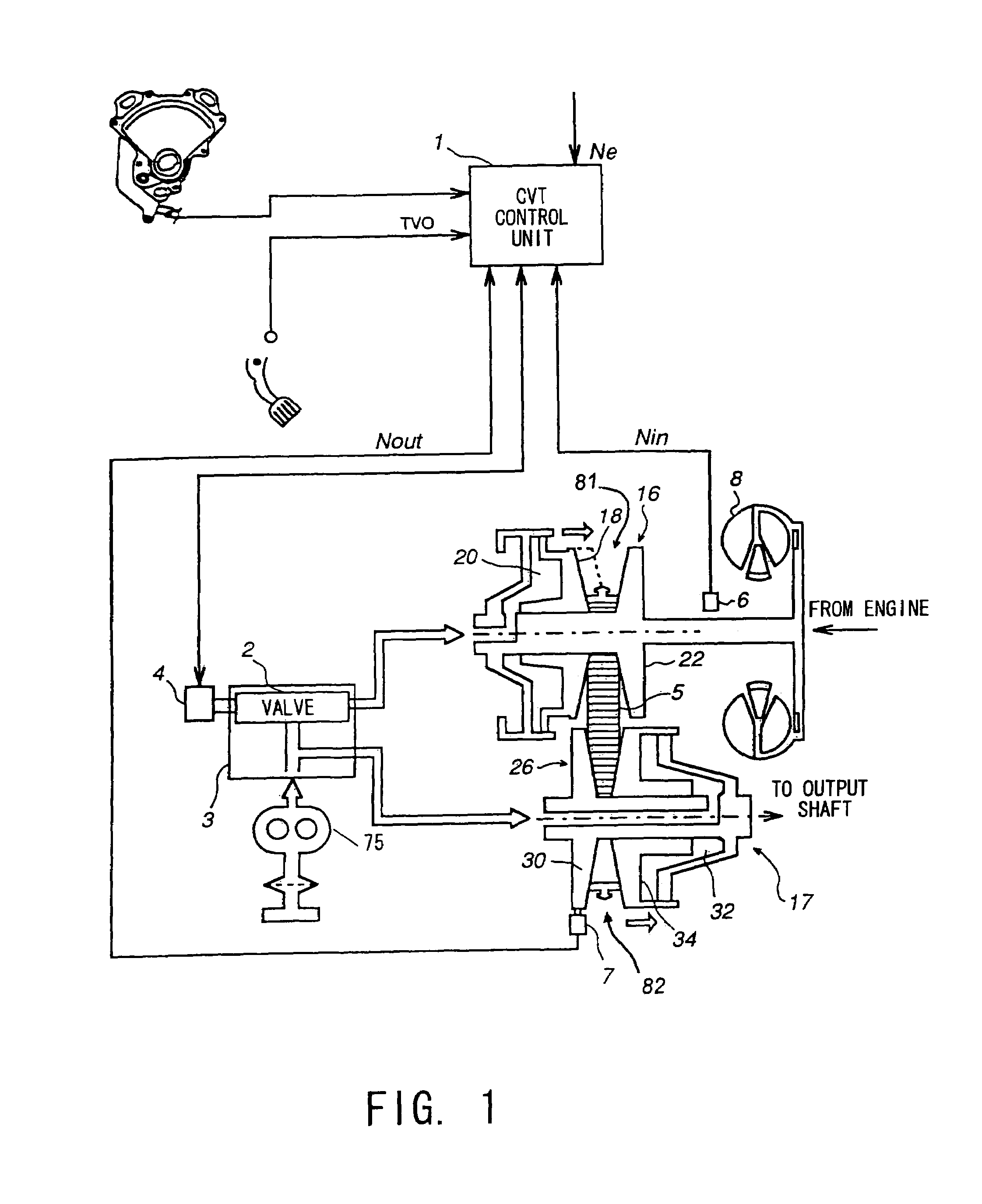
[0012]Referring to FIG. 1, the constitution of a V-belt continuously variable transmission will be described. A continuously variable transmission 17 comprises a drive pulley 16 to which torque is transmitted from an engine not shown in the drawing, and a driven pulley 26 which is connected to an output shaft. The drive pulley 16 and driven pulley 26 are variable pulleys having V-shaped pulley grooves 81, 82 with variable width. Here, the cross section of the pulley grooves 81, 82 along the radial direction of the pulley is V-shaped. A metallic V-belt 5 having a V-shaped cross section is wound around the drive pulley 16 and driven pulley 26, thereby interlocking the drive pulley 16 and driven pulley 26. The metallic V-belt 5 comprises a metal ring and metal elements supported by the metal ring. The metal elements come into contact with the surface of the pulley grooves 81, 82 and apply torque to the drive and driven pulleys 16, 26.

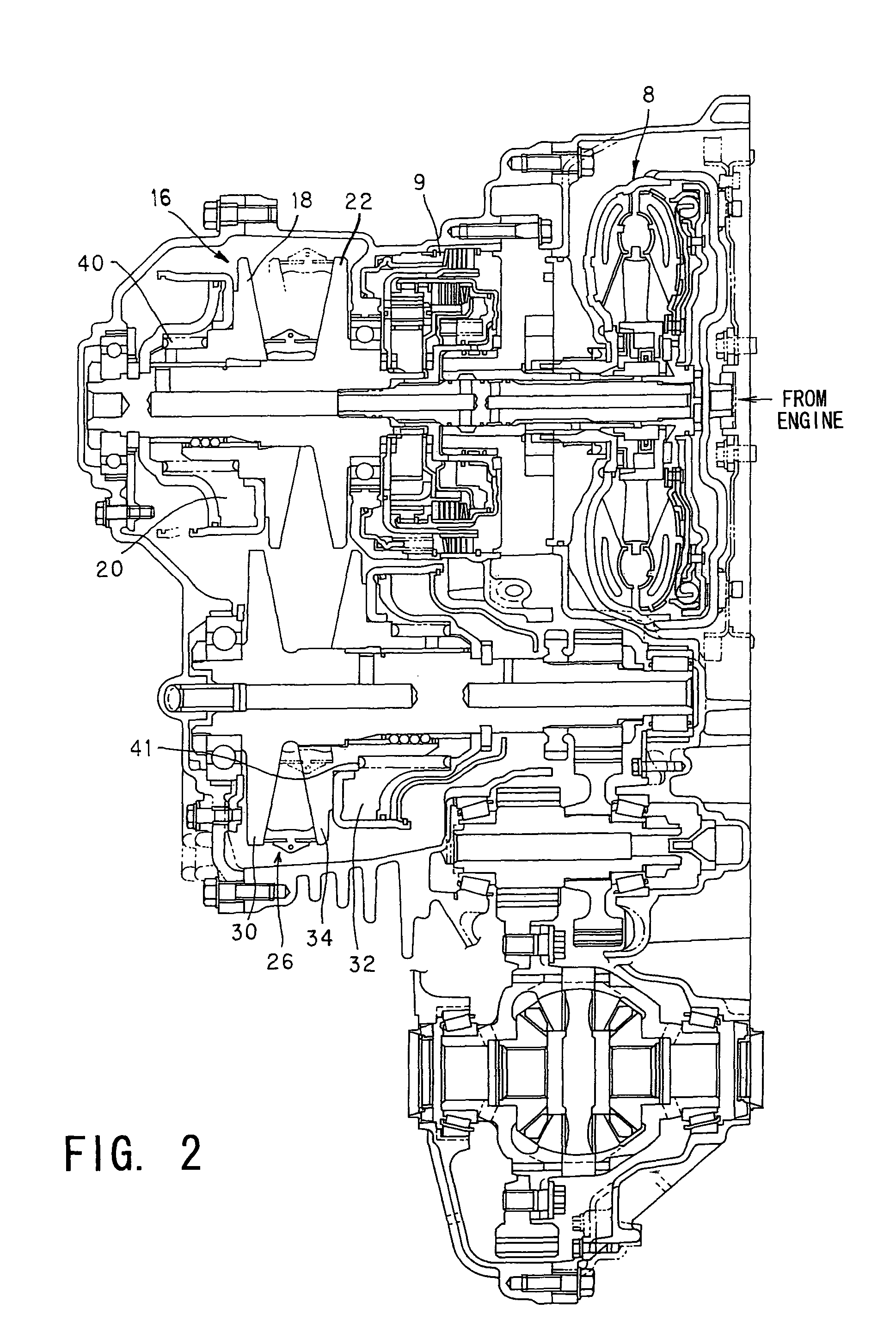
[0013]The drive pulley 16 comprises a fixed disk 22 ...


PUM


Abstract

A continuously variable transmission includes: (a) a drive pulley and a driven pulley in which the pulley width between a fixed disk and a movable disk may be varied in accordance with oil pressure, (b) a V-belt, which is wound around the drive pulley and driven pulley, and (c) a clutch for controlling the transmission of torque from an engine to the drive pulley. The continuously variable transmission further has a first spring for constantly urging the movable disk of the drive pulley to the fixed disk side and a second spring for constantly urging the movable disk of the driven pulley to the fixed disk side.

Description

FIELD OF THE INVENTION[0001]This invention relates to a belt-type continuously variable transmission (belt CVT).BACKGROUND OF THE INVENTION[0002]In a vehicle which uses a belt-type continuously variable transmission, engine torque is transmitted through an input shaft to a drive pulley of the belt-type continuously variable transmission. The torque is transmitted through a metal belt from the drive pulley to a driven pulley and then transmitted through an output shaft and a differential gear from the driven pulley to a driving wheel. A clutch for controlling the transmission of torque to the driving wheel is typically positioned downstream of the transmission in respect of the flow of torque. By disengaging the clutch when the vehicle is towed while the driving wheel is in contact with a road surface, the rotation of the driving wheel is not transmitted to the transmission.[0003]In one type of vehicle, however, the clutch is disposed between the engine and the belt-type continuously...

Claims


Application Information

Patent Timeline
IPC IPC(8): F16H59/00F16H55/56F16H9/18F16H9/12F16H61/662F16H63/06
CPCF16H63/067F16H55/56F16H61/12F16H2061/66295F16H61/66272F16H9/12
Inventor KURODA, SHOJIROWATABE, YUSUKE
Owner JATCO LTD
Why Eureka
Try Eureka