Solid electrolyte fuel cell system

Active Publication Date: 2010-11-04
NISSAN MOTOR CO LTD
View PDF19 Cites 8 Cited by
  • Summary
  • Abstract
  • Description
  • Claims
  • Application Information

AI Technical Summary

Benefits of technology

[0008]In the case of the methods of heating the reformer with means other than the off gas, however, the cell stack assembly increases the amount of heat generation to increase the output, and at the same time the heated reformed gas is supplied from the reformer heated by another heat source. Consequently, these methods might cause overheat of the cell stack assembly, thereby decrease the

Problems solved by technology

However, the application of this fuel cell system is difficult for electric power sources of vehicles such as electric vehicles.
However, the fuel cell system of the above-ment

Method used


Image

  • Solid electrolyte fuel cell system
  • Solid electrolyte fuel cell system
  • Solid electrolyte fuel cell system

Examples


first embodiment

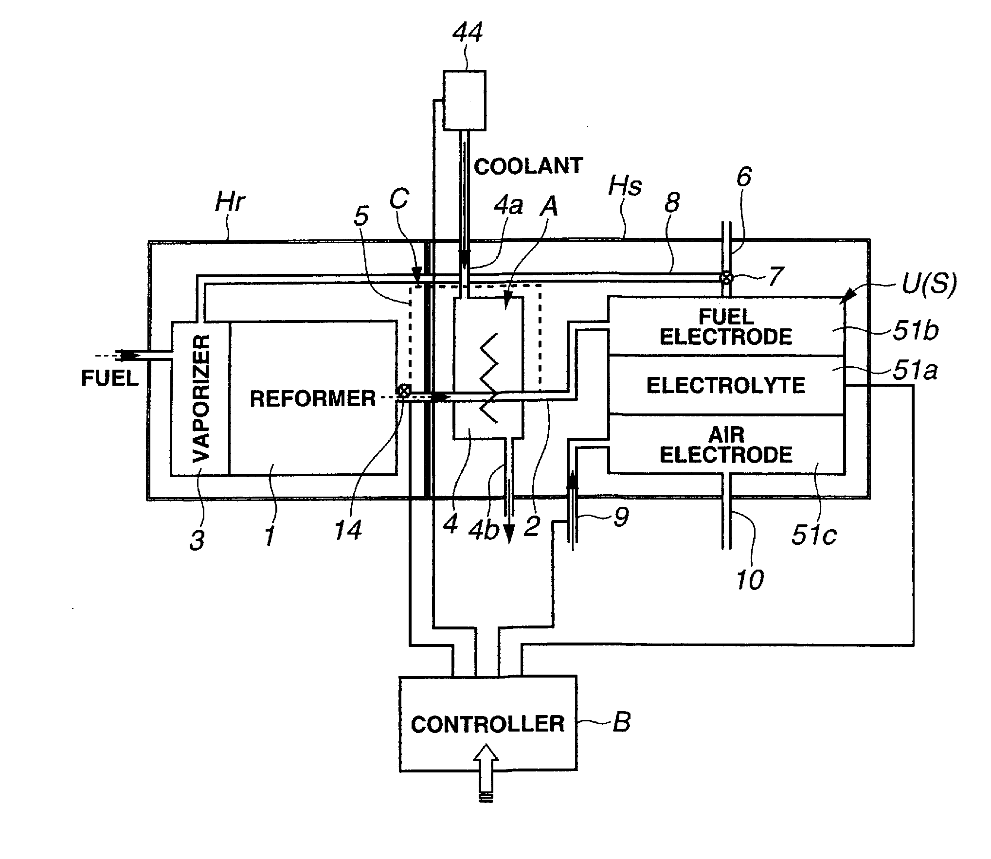
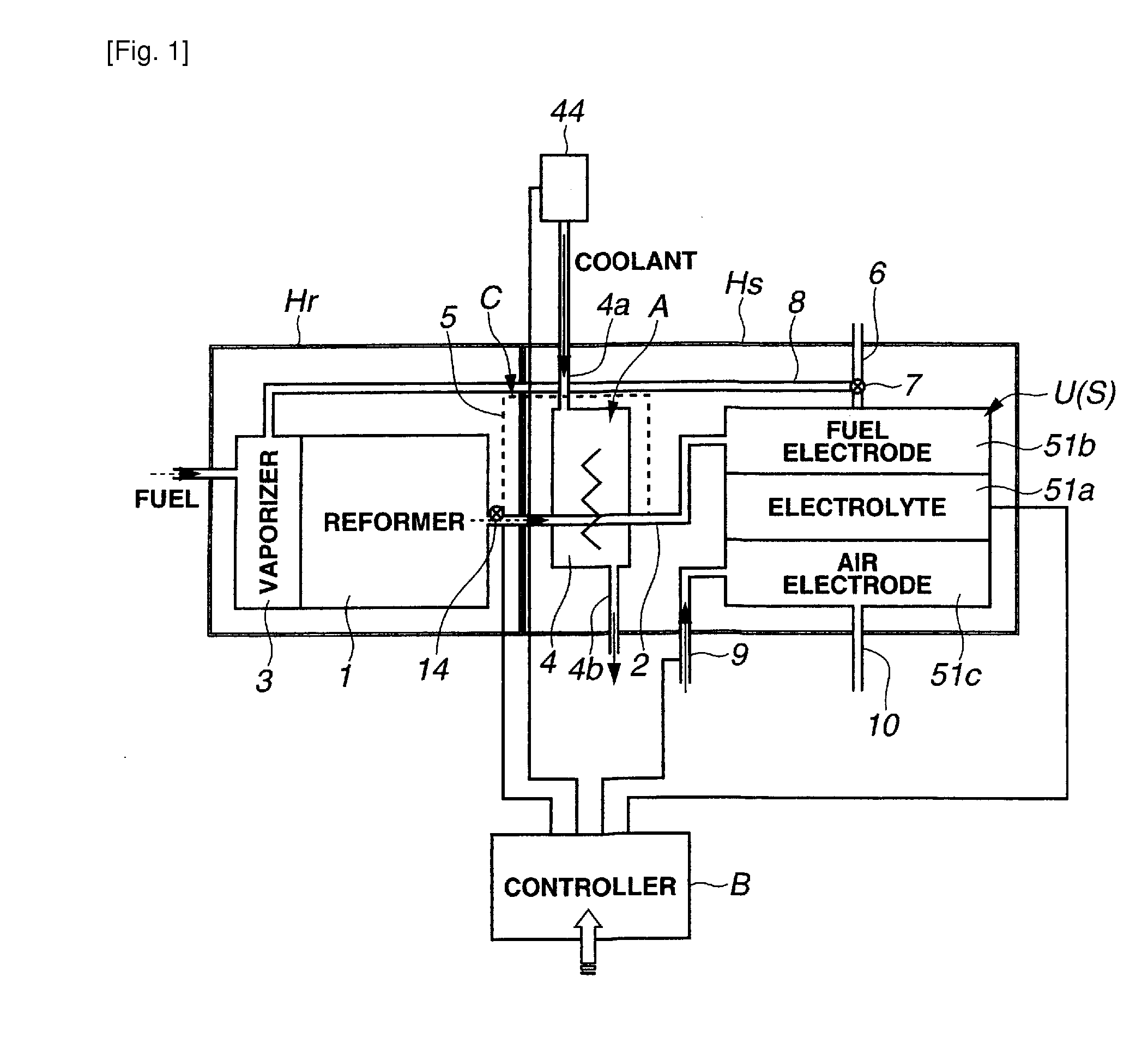
[0022]FIG. 1 shows a solid electrolyte fuel cell system or apparatus according to the present invention. The fuel cell system shown in FIG. 1 includes a reformer 1 for producing a reformed gas, and a stack structure S including a stack of cell units U. Reformer 1 of this example produces a hydrogen-rich reformed gas from fuel, oxygen and water. Each of the cell units U receives the supply of the reformed gas and air, and produces electricity.

[0023]The fuel cell system of FIG. 1 further includes a reformed gas cooler A which can serve as a component of a reformed gas cooling means for cooling the reformed gas supplied from reformer 1 to stack structure S, and a temperature control section which can serve as a component of a temperature controlling means for controlling the temperature of stack structure S. The temperature control section of this embodiment is configured to control the operation of the reformed gas cooler A. According to the first embodiment, the temperature control s...

second embodiment

[0060]In the second embodiment, the reformer 1 (together with vaporizer 3), the heat exchanger 4 and the stack structure S are separately encased in heat insulating containers Hr, Hh and Hs. This insulating container structure composed of the container Hr enclosing reformer 1, the container Hh enclosing heat exchanger 4, and the container Hs enclosing stack structure S can insulate the reformer 1, heat exchanger 4 and stack structure S from one another thermally, and restrains the heat transfer or the exchange of heat therebetween, except the heat transfer through the reformed gas. By doing so, this insulating container structure composed of the separate insulating containers Hr, Hh and Hs can improve the effect of the control of the temperature of stack structure S by the control of heat quantity of the reformed gas, thereby stabilize the temperature of stack structure S, and further improve the controllability or following characteristic to the load varying operation (as in a vehi...

third embodiment

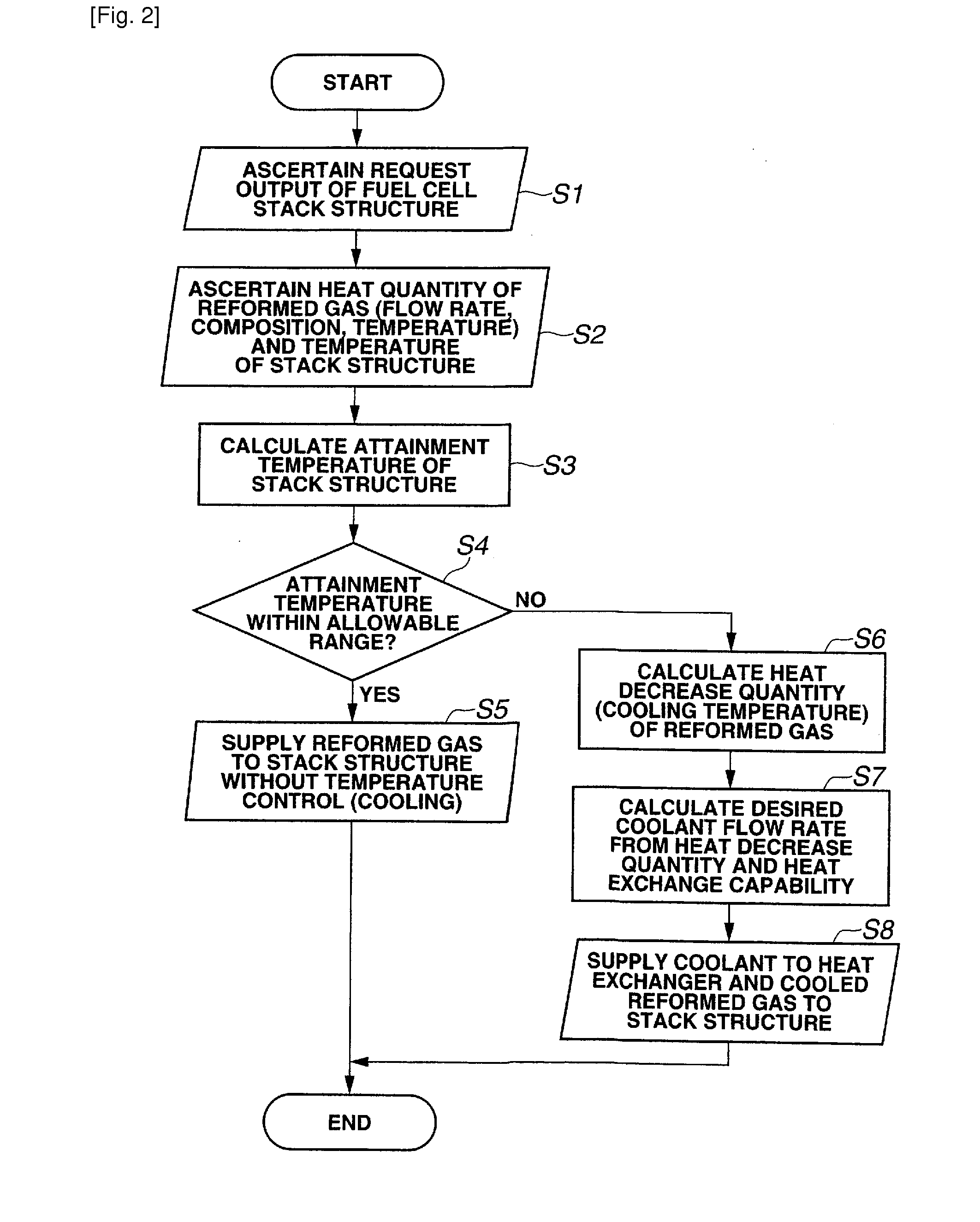
[0073]FIG. 6 shows a control process performed by the temperature controller B in the solid electrolyte fuel cell system according to the Steps S1˜s4 and S11˜S15 are substantially identical to the steps S1˜S4 and S11˜S15 of FIG. 4, so that the explanation is omitted.

[0074]When the attainment temperature of stack structure S exceeds the allowable range, and the answer of S4 is NO, then controller B proceeds from S4 through S12, S13 and S14, to a step S21. At S21, controller B ascertains the sensed reformed gas temperature of the reformed gas after the heat exchange sensed by temperature sensor 15 an the sensed air temperature of the air (generating air) after the heat exchange sensed by temperature sensor 16. Then, at a next step S22, controller B examines whether a reformed gas temperature difference between the sensed reformed gas temperature and an estimated reformed gas temperature is lower than or equal to a first predetermined value, and whether an air temperature difference b...


PUM


Abstract

A solid electrolyte fuel cell system includes a reformer to produce a hydrogen-rich reformed gas from fuel, oxygen and water, and a stack structure including a stack of fuel cell units each receiving supply of the reformed gas and air, and producing electricity. The fuel cell system further includes a reformed gas cooler to cool the reformed gas supplied from the reformer to the stack structure, and a temperature control section to control operation of the reformed gas cooler in accordance with an operating condition such as a request output of the stack structure. The reformed gas cooler includes a device such as a heat exchanger for cooling the reformed gas with a coolant such as air.

Description

TECHNICAL FIELD[0001]The present invention relates to a fuel cell system or apparatus including a reformer to produce a reformed gas, and a stack structure including a stack of fuel cell units, and technique (such as system and / or process) of controlling the temperature of the stack structure.BACKGROUND ART[0002]A published Japanese Patent Application, Kokai No. 2005-183375 shows a solid electrolyte type fuel cell system including a cell stack assembly composed of a plurality of cell stacks, a gas manifold provided with the cell stack assembly, a reformer to produce a hydrogen-rich reformed gas by steam reforming, and a reformed gas supplying tube connecting the reformer to the gas manifold, which are provided inside a housing. This fuel cell system is arranged to heat the reformer with an off gas discharged from the cell stack assembly.[0003]There are three different reforming reactions performed in the reformer. Steam reforming reaction is endothermic, and partial oxidation reacti...

Claims


Application Information

Patent Timeline
IPC IPC(8): H01M8/06
CPCH01M8/04007H01M8/04014Y02E60/50H01M8/0612H01M8/2475H01M8/04089
Inventor TAKEUCHI, KAZUFUMIMIWA, HIROMICHIHATANO, MASAHARUKUSHIBIKI, KEIKOYAGUCHI, TATSUYA
Owner NISSAN MOTOR CO LTD
Why Eureka
Try Eureka