
Fuel cell having optimized pattern of electric resistance

Inactive Publication Date: 2006-03-07
DELPHI TECH INC
View PDF13 Cites 8 Cited by
  • Summary
  • Abstract
  • Description
  • Claims
  • Application Information

AI Technical Summary

Benefits of technology

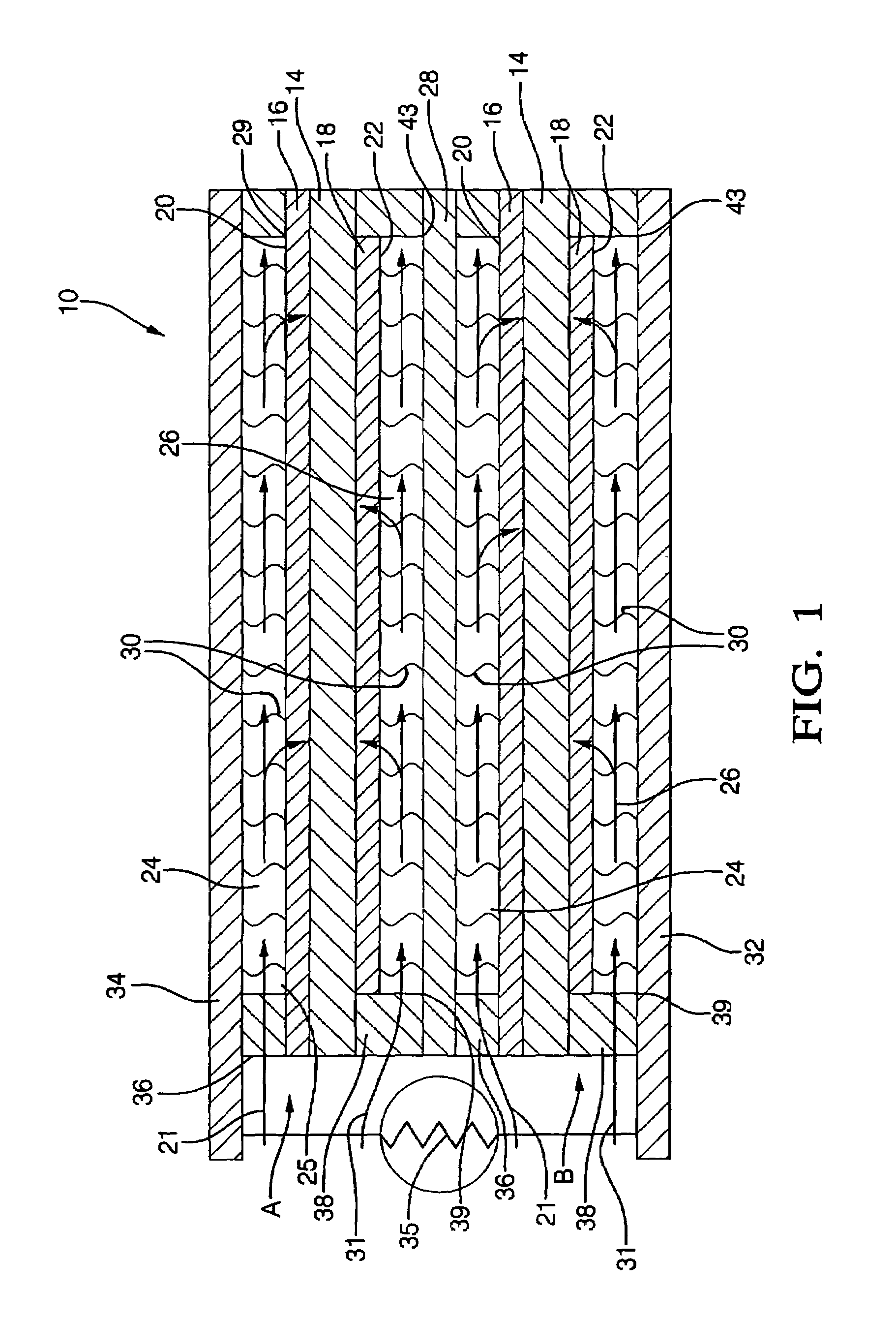
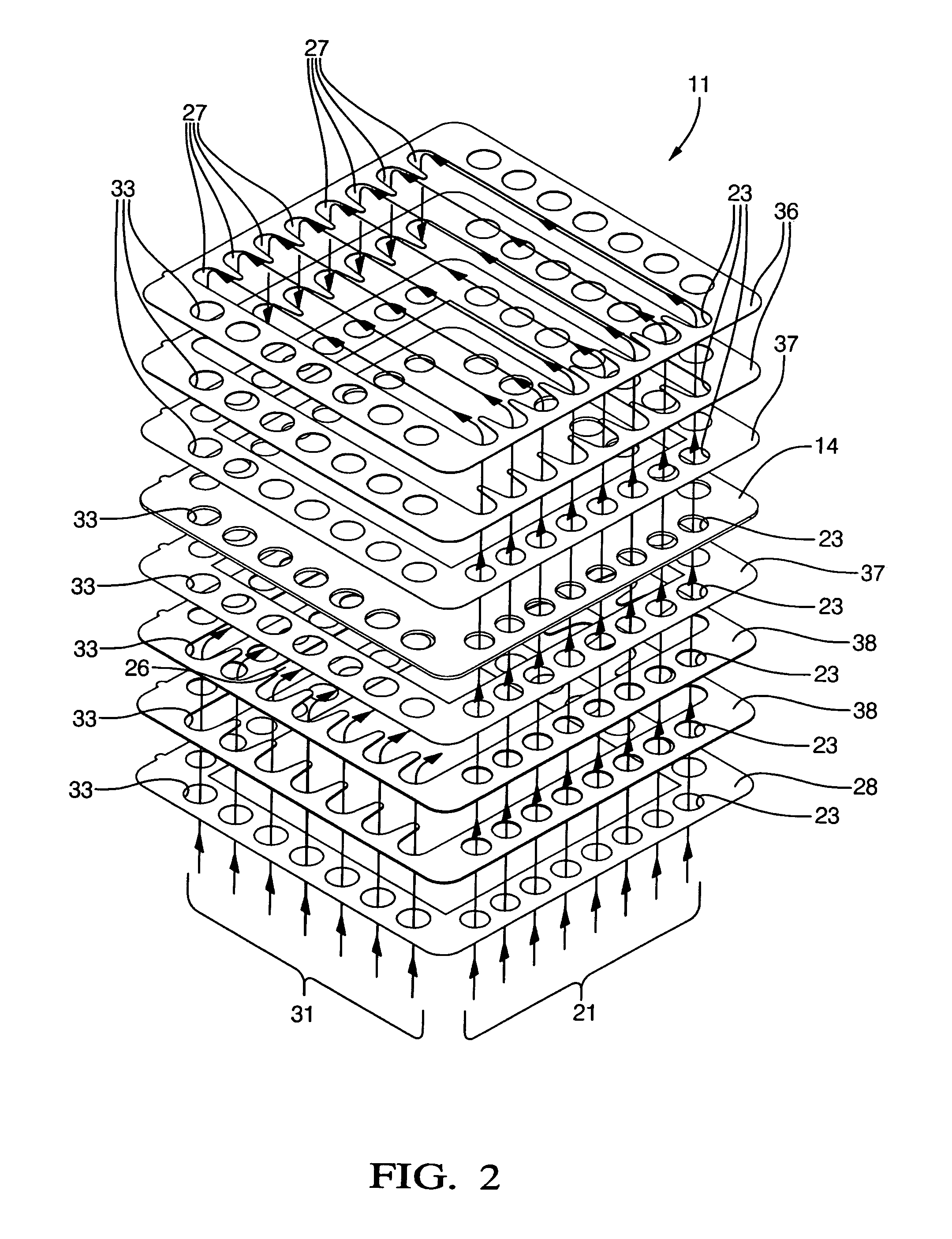
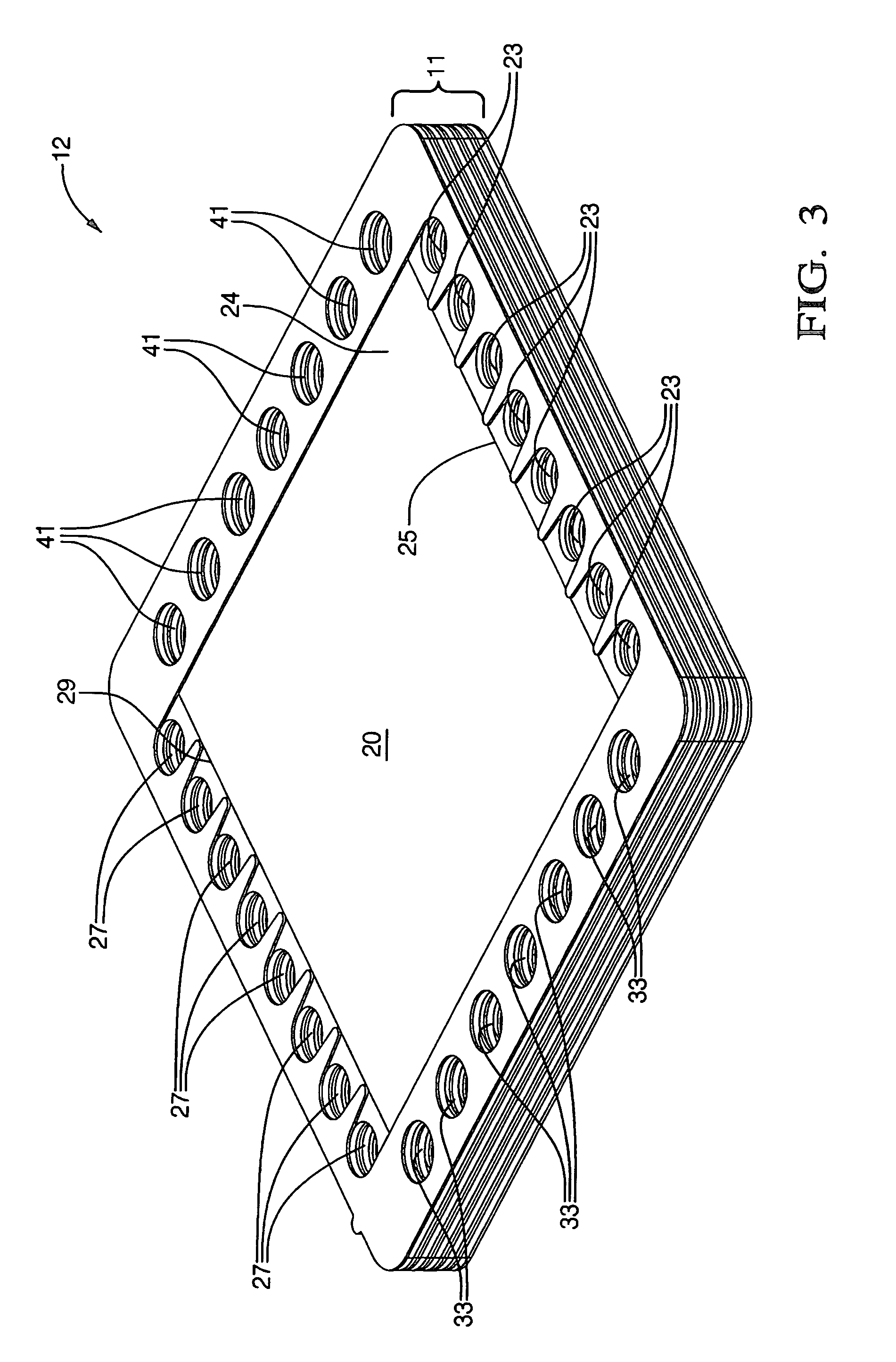
[0009]Briefly described, a fuel cell in accordance with the invention has a non-uniform electrical resistivity over the flow area of the cell. Resistance is higher in areas of the cell having locally low levels of hydrogen than in areas having locally high levels of hydrogen. Since the rate of oxygen ion migration through the electrolyte is inversely proportional to the resistance of the circuit at any give point in the cell, the areal pattern of resistance is shaped in inverse proportion to the steady-state hydrogen concentration. Excess oxygen ion migration and buildup is suppressed in regions having low hydrogen concentration and is correspondingly increased in regions having a surfeit of hydrogen. Thus, destructive oxidation of the anode is prevented and a greater percentage of the hydrogen passed into the cell is consumed, thereby increasing electric output.

Problems solved by technology

An important limitation to improving power densities and increasing fuel utilization in a solid oxide fuel cell is localized fuel starvation in regions of the anode.

Method used


Image

  • Fuel cell having optimized pattern of electric resistance
  • Fuel cell having optimized pattern of electric resistance
  • Fuel cell having optimized pattern of electric resistance

Examples


first embodiment

[0039]In a first embodiment, the chemical composition of either the cathode or the anode itself is varied regionally to increase or decrease local conductivity. The cathode comprises, for example, a chemical composition of lanthanum strontium manganate of lanthanum strontium iron. In the embodiment, the atomic proportion of lanthanum to strontium in the composition is varied across the cathode non-uniformly so that the atomic proportion is increased in regions of the cathode where high concentrations of hydrogen are found to exist. For example, in areas of high hydrogen concentration where greater conductivity is desired, the atomic proportion of lathanum to strontium may by 80% to 20%, respectively, while in areas of low concentration, the proportion would be reversed. The chemical composition of the anode can also be varied. The anode comprises a mixture of a conductive material, for example, nickel, and a dielectric material, for example YSZ. The nickel percentage is varied non-u...

seventh embodiment

[0045]Typically, the thickness of the electrolyte element is approximately 1 micron. In a seventh embodiment, the thickness of the electrolyte element is varied regionally to increase or decrease local conductivity. Where areas of low hydrogen concentration exists, the electrolyte is made thicker to decrease conductivity, and vice versa. The proper thickness gradient for a given fuel cell stack are readily determinable without undue experimentation.

[0046]Techniques for forming the dielectric deposits on the anodes, cathodes, interconnects, and current collectors, for varying the thickness of the electrolyte element, for forming protrusions on the interconnects and current collectors, and for varying the nickel content of the anodes, or the atomic proportions of the lanthanum and strontium of the cathode in the embodiments just recited are well within the skill of one skilled in the art of fuel cell manufacture; therefore, such techniques need not be recited here.

[0047]Also, in the e...


PUM


Abstract

A fuel cell having a non-uniform electrical resistivity over the flow area of the cell. Resistance is higher in areas of the cell having locally low levels of hydrogen than in areas having locally high levels of hydrogen. Excess oxygen ion migration and buildup is suppressed in regions having low hydrogen concentration and is correspondingly increased in regions having a surfeit of hydrogen. Destructive oxidation of the anode is suppressed and a greater percentage of the hydrogen passed into the cell is consumed, thereby increasing electric output.

Description

TECHNICAL FIELD[0001]The present invention relates to fuel cells; more particularly, to such fuel cells having a solid oxide electrolyte; and most particularly, to such a fuel cell wherein the permeation of oxygen ions to the anode is controlled by controlling the electrical resistance of the cell non-uniformly.BACKGROUND OF THE INVENTION[0002]Fuel cells which generate electric current by controllably combining elemental hydrogen and oxygen are well known. In one form of such a fuel cell, an anodic layer and a cathodic layer are separated by an electrolyte formed of a ceramic solid oxide. Such a fuel cell is known in the art as a “solid oxide fuel cell” (SOFC). Either pure hydrogen or reformate is flowed along the outer surface of the anode and diffuses into the anode. Oxygen, typically from air, is flowed along the outer surface of the cathode and diffuses into the cathode. Each O2 molecule is split and reduced to two O−2 ions at the cathode / electrolyte interface. The oxygen ions d...

Claims


Application Information

Patent Timeline
IPC IPC(8): H01M8/04H01M4/86H01M8/02H01M8/12
CPCH01M4/8626H01M8/0247H01M8/0256H01M4/9033H01M4/9066H01M8/0232Y02E60/525H01M2008/1293Y02E60/50H01M8/0236
Inventor KEEGAN, KEVIN R.ENGLAND, DIANE M.
Owner DELPHI TECH INC
Learn More