Method and ring oscillator circuit for measuring circuit delays over a wide operating range

a technology of ring oscillator circuit and delay time, which is applied in the field of testing circuits, can solve the problems of limited measurement accuracy of measuring equipment, difficult or impossible direct measurement, and short propagation delay time of digital circuit on semiconductor dies

Inactive Publication Date: 2006-05-16
INT BUSINESS MASCH CORP
View PDF5 Cites 19 Cited by
  • Summary
  • Abstract
  • Description
  • Claims
  • Application Information

AI Technical Summary

Benefits of technology

[0012]The detected transition is used to start and end the next clock pulse by using a pulse generator circuit that generates a pulse of fixed width in response-to the detected transition. Thus, the ring oscillator will oscillate no matter the length of the measured delay, making the circuit suitable for measurement of evaluate changes due to leakage (long delay) as well as those due to the logic implementation (relatively short delay).

Problems solved by technology

Ring oscillators have been commonly used in evaluation of digital circuits delay times. Since the propagation delay time of digital circuits on a semiconductor die can be very short, especially at a single-gate level, direct measurement is difficult or impossible.
The measuring equipment accuracy is generally limited by the same constraints as the circuit under test, and will typically have resolution and accuracy limitations that do not even approach the delay time of a single gate integrated on a semiconductor die.
However, the ring oscillator described in the above-referenced patent includes design constraints that limit the range over which the evaluation delay time of the dynamic circuit under test can vary, while still providing an accurate measurement.
Thus, the circuit described in the above-referenced patent requires control of two parameters: the maximum one-shot time and the minimum evaluate pulse width, making control of the circuit over wide operating ranges difficult or impossible.

Method used


Image

  • Method and ring oscillator circuit for measuring circuit delays over a wide operating range
  • Method and ring oscillator circuit for measuring circuit delays over a wide operating range
  • Method and ring oscillator circuit for measuring circuit delays over a wide operating range

Examples


Embodiment Construction

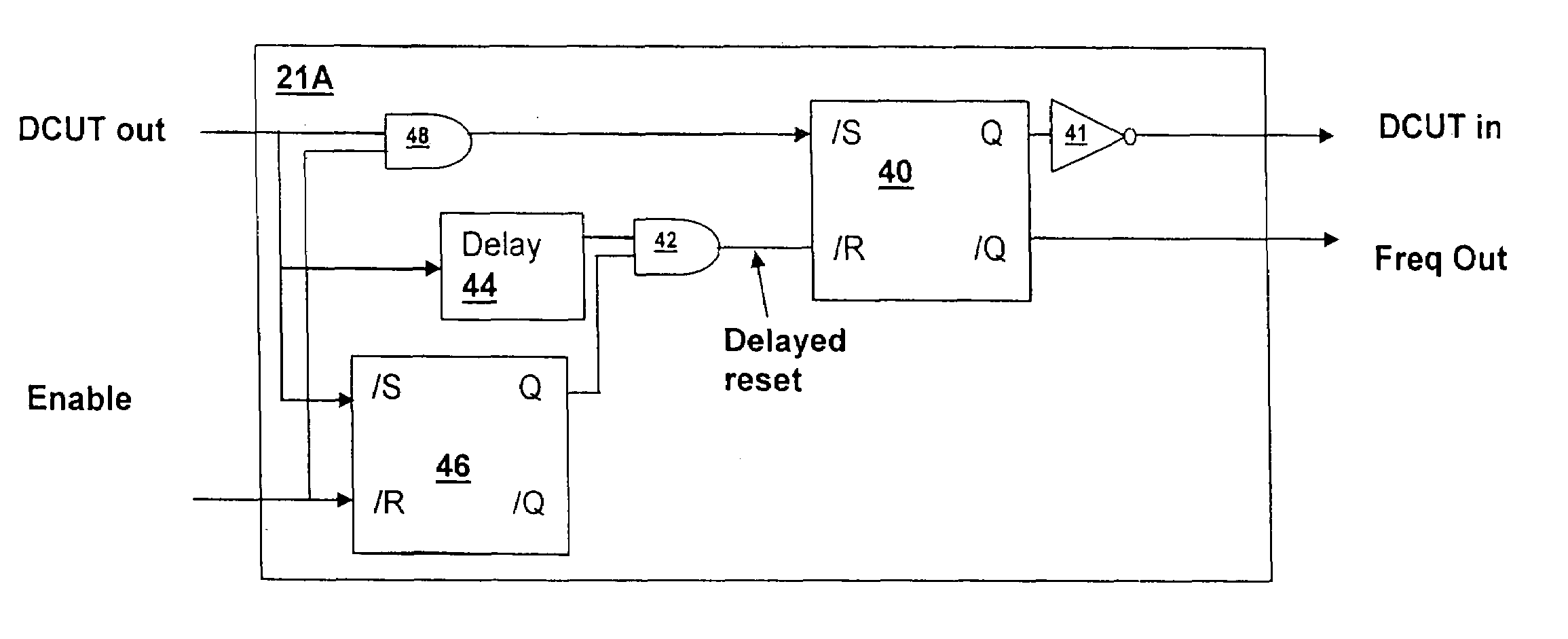
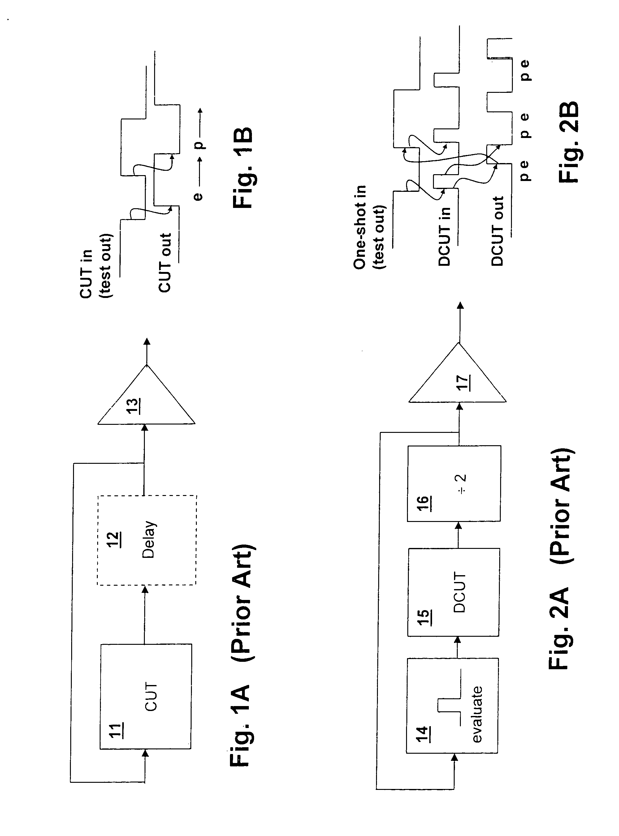
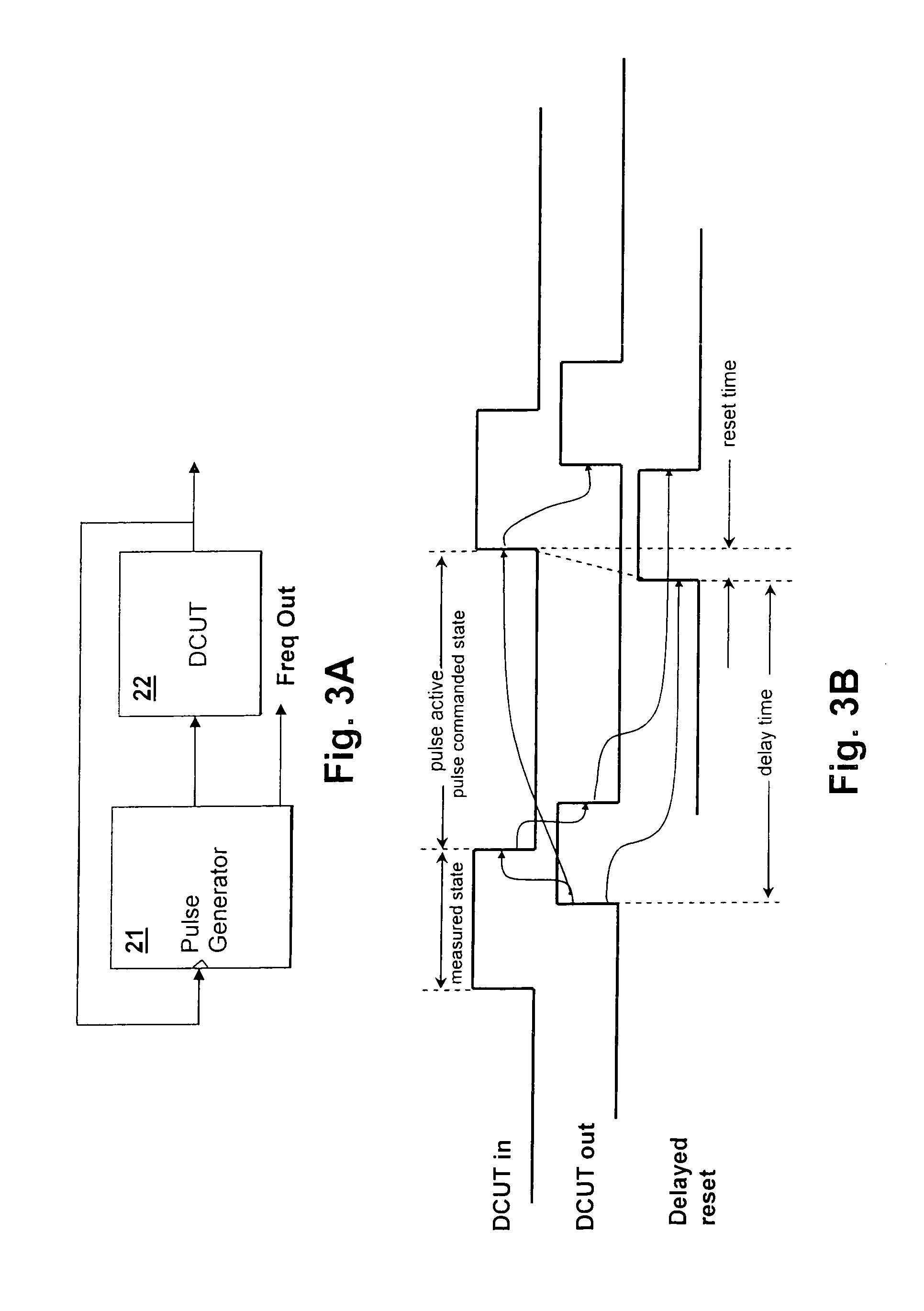
[0022]With reference now to the figures, and in particular with reference to FIG. 1A, there is depicted a prior art test circuit that forms a ring oscillator for generating a frequency that depends on the logic delays of the circuit chain. Circuit under test 11 is configured to provide an inverting path in combination with a delay circuit 12 so that changes occurring on the output of circuit under test 11 will cause further changes in the output of circuit under test 11 as they are returned to the input of circuit under test 11 after being delayed by delay circuit 12. Buffer 13 provides an output for measuring the frequency of the signal generated by the ring oscillator circuit, which has a period determined by the delay of delay circuit 12 and the sum of the two transition delay times of circuit under test 11.

[0023]Referring to FIG. 1B, the signals in the circuit of FIG. 1A are depicted in a timing diagram. The edge relationships are drawn-with arrows showing the causal action of e...


PUM


Abstract

A method and ring oscillator circuit for measuring circuit delays over a wide operating range permits improved analysis of dynamic circuits. A pulse generator circuit provides a pulse to an input of a dynamic circuit under test, which may be a pre-charge or evaluation pulse that is triggered by a transition of an output of the dynamic circuit that occurs during the state opposite that of the state commanded by the pulse. The action of the circuit provides for measuring any amount of delay to the next transition in the opposite state irrespective of the pulse width. By providing a wide-range of operation, characteristics such as leakage, charge sharing, data dependent node capacitance, previous value dependence as well as other dynamic circuit behaviors may be determined. The ring oscillator circuit includes an enable start circuit that causes a first pulse to be generated by the one-shot when the ring oscillator circuit is enabled.

Description

BACKGROUND OF THE INVENTION[0001]1. Technical Field[0002]The present invention relates generally to test circuits for evaluating the performance of circuits incorporated on a semiconductor die, and more particularly, to a ring oscillator circuit for determining delays of digital circuits.[0003]2. Description of the Related Art[0004]Ring oscillators have been commonly used in evaluation of digital circuits delay times. Since the propagation delay time of digital circuits on a semiconductor die can be very short, especially at a single-gate level, direct measurement is difficult or impossible. The measuring equipment accuracy is generally limited by the same constraints as the circuit under test, and will typically have resolution and accuracy limitations that do not even approach the delay time of a single gate integrated on a semiconductor die. The use of a ring oscillator allows a simple frequency measurement to provide useful information about the delay time of a digital circuit. ...

Claims


Application Information

Patent Timeline
Patent Type & Authority Patents(United States)
IPC IPC(8): H03B27/00G01R23/00H03B1/00
CPCH03K3/0315G01R31/31725
Inventor BELLUOMINI, WENDY ANNMARTIN, ANDREW KENNETHMCDOWELL, CHANDLER TODD
Owner INT BUSINESS MASCH CORP
Why Eureka
Try Eureka