Graphic editing apparatus graphic editing method and storage medium on which is recorded a program for graphic editing

a graphic editing and graphic editing technology, applied in the field of graphic editing apparatus, can solve the problems of increasing the difficulty of user operation in the kind of editing process, increasing the difficulty of user operation, and increasing the difficulty of user operation, and achieve the effect of simple operation

Inactive Publication Date: 2006-05-16
FUJITSU LTD
View PDF17 Cites 18 Cited by
  • Summary
  • Abstract
  • Description
  • Claims
  • Application Information

AI Technical Summary

Benefits of technology

[0016]An objective of the present invention is to make operation simple in the case where another object is inserted between objects previously connected.

Problems solved by technology

However, according to conventional application software, it requires much work for a user to operate in that kind of edit process, and the user often felt it was troublesome.
This problem becomes more serious in particular when a new object is inserted in a graphic where a connection relation between objects is complicated.
In this way, as the number of lines to be deleted or the number of lines to be newly set increases, the amount of work and working time of a user also increase.
The probability of errors which occur when a line is deleted or set, also increases.
This problem not only occurs in application software for drawing flowcharts, but it also occurs in software for drawing graphics and software for drawing circuit diagrams, etc.

Method used


Image

  • Graphic editing apparatus graphic editing method and storage medium on which is recorded a program for graphic editing
  • Graphic editing apparatus graphic editing method and storage medium on which is recorded a program for graphic editing
  • Graphic editing apparatus graphic editing method and storage medium on which is recorded a program for graphic editing

Examples


Embodiment Construction

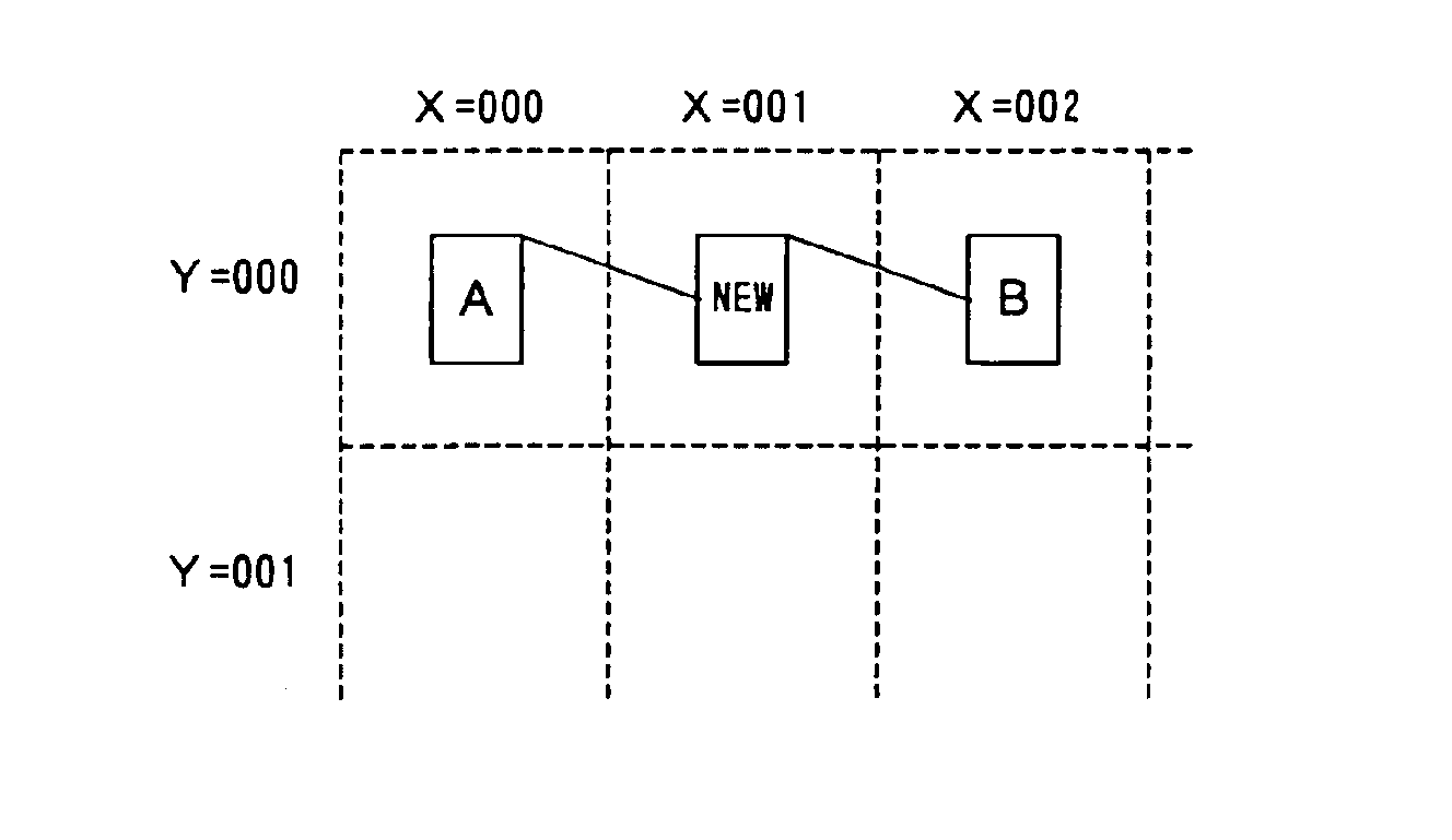
[0076]The graphic editing method of the present invention relates to a method for editing a graphic, etc., displayed on the monitor of a computer 1, such as shown in FIG. 3. Although a graphic, etc., is basically edited by the user operation of a mouse 2, it can also be edited by inputting an instruction from a keyboard. For the following preferred embodiments, for example, the graphic editing method of the present invention is described below using a flowchart as its target. In a flowchart, a graphic unit corresponding to each step is handled as one “object”.

The First Preferred Embodiment

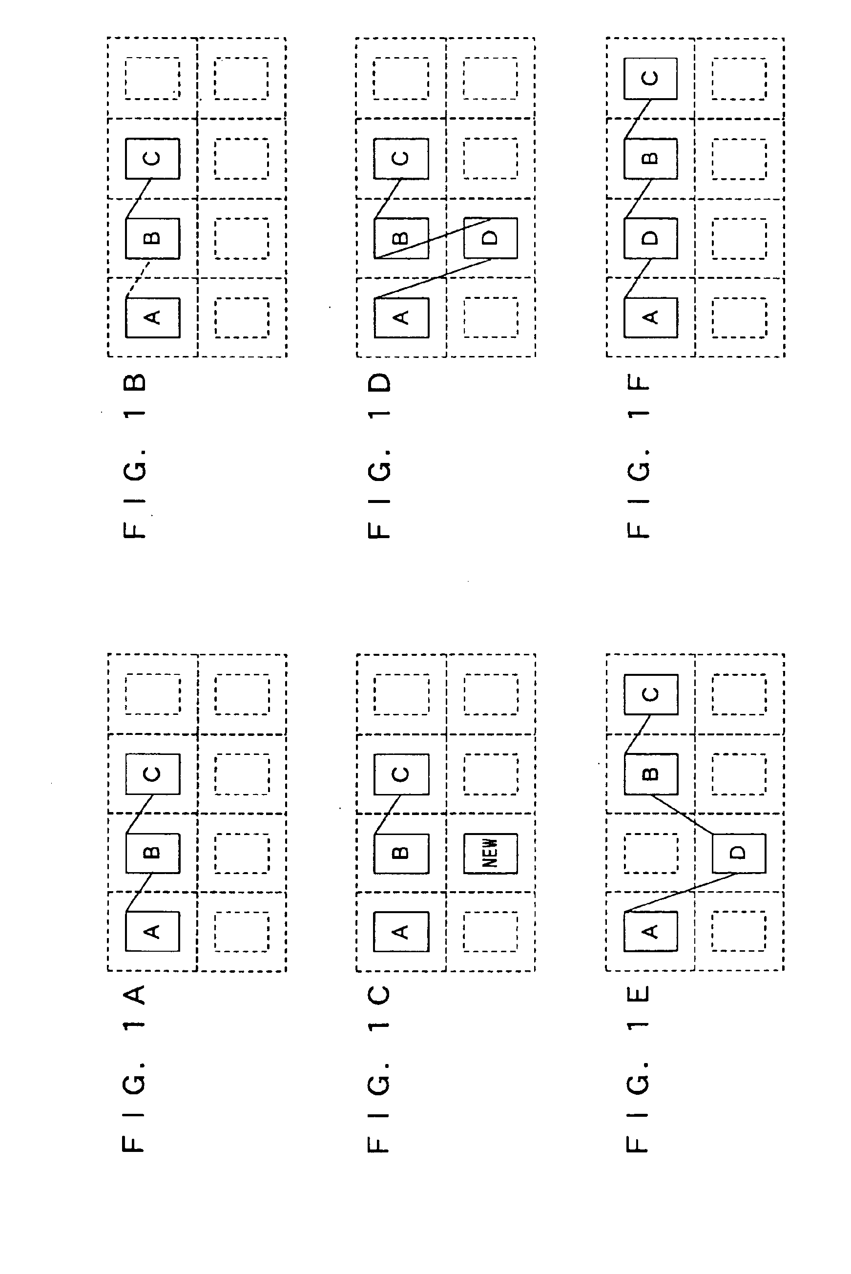
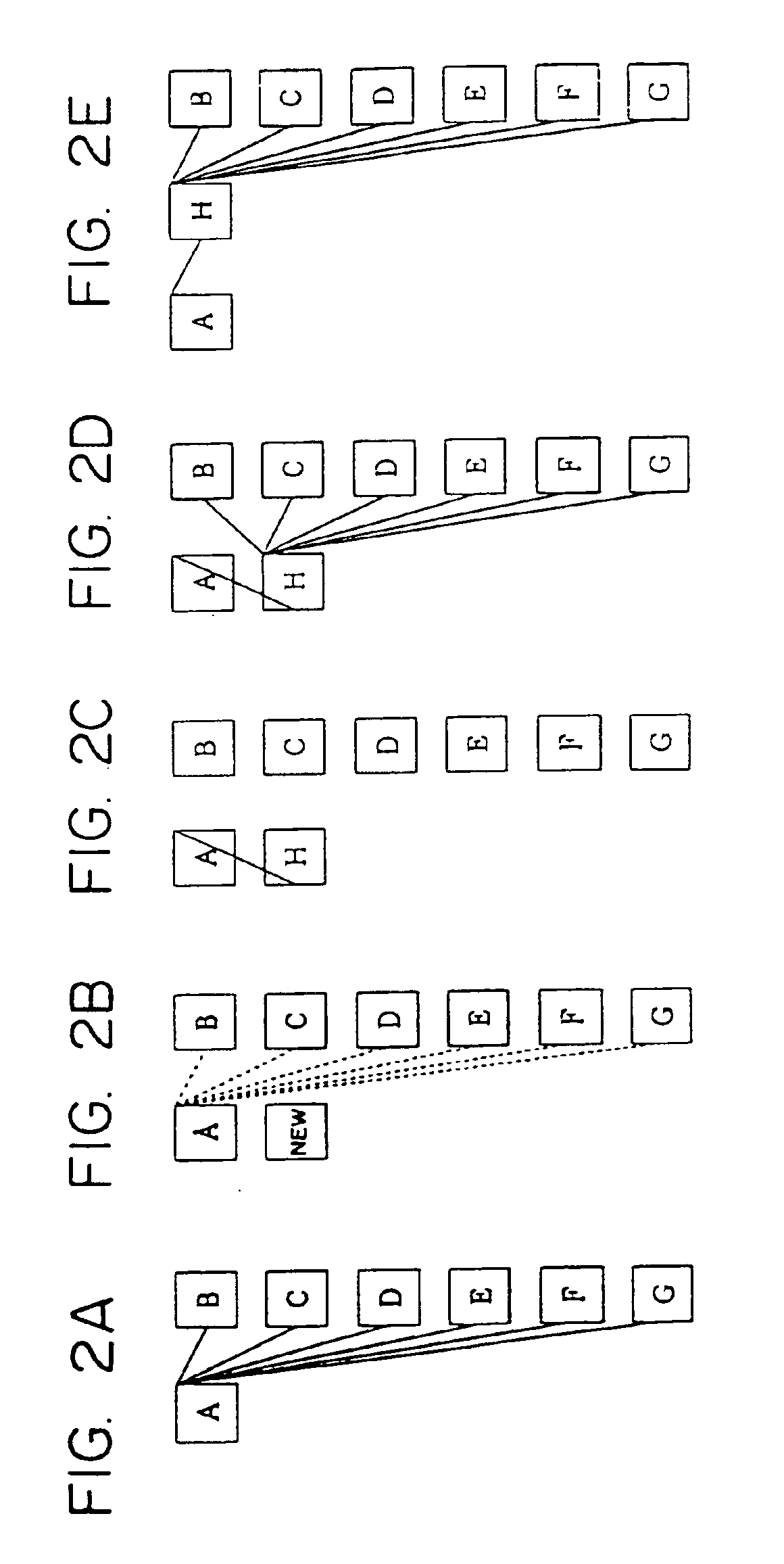
[0077]FIGS. 4A through 4D explain the basic operation in the first preferred embodiment of the present invention. Here, a graphic (flowchart) where object A, object B and object C are connected in this order is displayed, and a case where a newly created object D is inserted between objects A and B is explained. It is assumed that the graphic editing software of the first preferred embodiment provi...


PUM


Abstract

A flowchart including objects A through C is displayed on the monitor of a computer. If an object D is inserted between objects A and B, object D is dropped on a line AB. By this operation, objects A and D are automatically connected, and objects D and B are automatically connected.

Description

BACKGROUND OF THE INVENTION[0001]1. Field of the Invention[0002]The present invention relates to an apparatus or method for inserting another object between objects connected with each other.[0003]2. Description of the Related Art[0004]Today it is common for a variety of flowcharts to be drawn using a computer. Software, for example, “Power Point” (Microsoft), “Visio” (Visio), etc., with a function to draw a graphic, etc., are well known.[0005]A flowchart is used, for example, to indicate the procedure (or sequence) of a working process and the procedure of the process of a software program, and it usually includes a plurality of objects, and lines or connectors connecting the plurality of objects.[0006]FIG. 1A is an example of a flowchart displayed on the monitor of a computer. In this flowchart, three objects (objects A through C) are connected in alphabetical order. A box formed using dotted lines indicates a display area in a virtual coordinate system, and it is not actually dis...

Claims


Application Information

Patent Timeline
Patent Type & Authority Patents(United States)
IPC IPC(8): G06T11/20G06F17/00G06F9/00G09G5/00G06F9/06G06T11/00G06T11/80
CPCG06T11/206
Inventor SAITOU, NOBUHIRO
Owner FUJITSU LTD
Why Eureka
Try Eureka