Diffractive color filter

a color filter and diffractive technology, applied in the field of diffractive color filters, can solve the problems of reducing further to around 30% light utilization efficiency, a serious detriment to the potential 30% efficiency, etc., and achieves the effects of low cost, high-efficiency illumination, and economical method of displacing the image in tim

Inactive Publication Date: 2006-05-16
CORNING INC +1
View PDF47 Cites 18 Cited by
  • Summary
  • Abstract
  • Description
  • Claims
  • Application Information

AI Technical Summary

Benefits of technology

[0009]This small shifting of the picture must take place rapidly (i.e. at a fast field rate) but will be much less noticeable than the complete change of color that accompanies the typical field sequential color display. The dot sequential display of this invention differs from a field sequential display in that the former uses different sub-pixels or dots for each color component, whereas the latter successively uses the same pixels for each color component. The field sequential display suffers from a macro-color flicker effect that is very noticeable unless the field rate is much higher than 180 Hz.
[0010]Dot-sequential Color uses a single LCD (or DMD, etc.) imaging device at the desired final resolution, but creates 3 slightly displace

Problems solved by technology

The major drawback of this type of display is that one-third of the light emanating from the display (in the case of a single-chip DMD, transmitted through the color wheel and reflected off of the micromirror elements) is used at any one time, and due to a “dead-ban

Method used


Image

  • Diffractive color filter
  • Diffractive color filter
  • Diffractive color filter

Examples


Embodiment Construction

[0036]The present invention relates to pixelated electronic (e.g., liquid crystal display, digital micromirror device, etc.) projection displays, sometimes referred to as electronic display projectors. The invention includes a dot sequential color display system that may be used in such an electronic display projector. It will be appreciated, however, that the dot sequential color display system of the present invention could alternatively be used in other display applications.

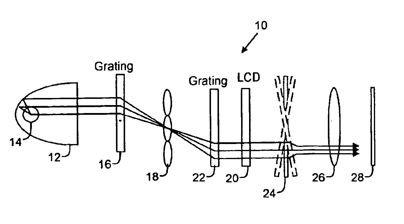
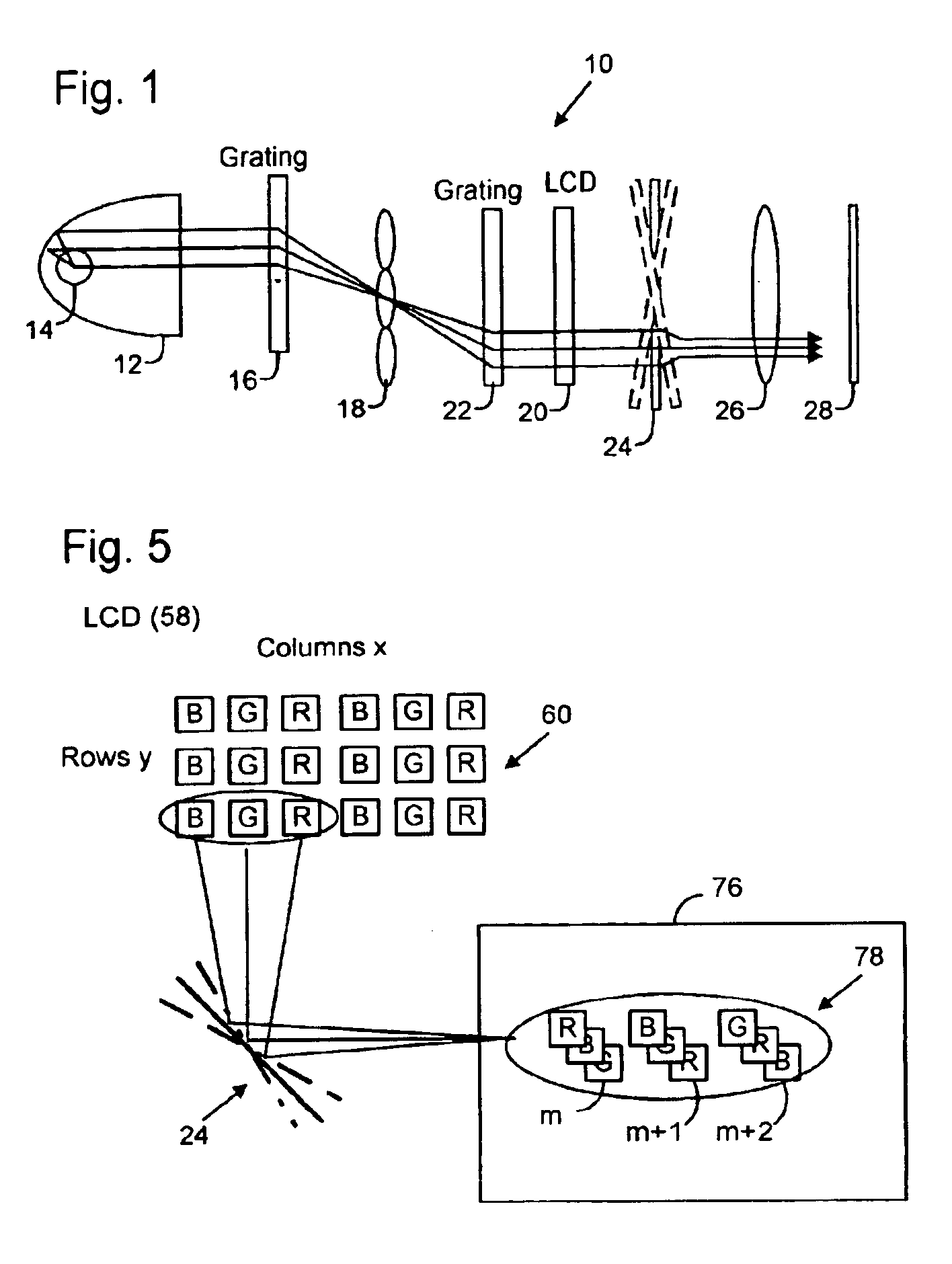
[0037]FIG. 1 is an optical schematic illustration of a dot sequential color display system 10 according to the present invention. A parabolic reflector 12 collects generally white light from a lamp 14 (e.g., an arc lamp) and directs the light in generally parallel rays to a first grating 16. Grating 16 disperses or separates color components of the light (e.g., red, green and blue “RGB”) and directs them to a microlens array 18 that focuses the dispersed light onto or toward a pixelated electronic display (e.g...


PUM


Abstract

A color display system includes a color light separator that separates incident white illumination light into red, green and blue wavelength bands to be directed to distinct color component sub-pixels (sometimes called dots) that are arranged in a dot-matrix, color triad arrangement (e.g., stripe or delta) to form individual picture elements (pixels) on a pixelated electronic image device (e.g., LCD of DMD). The entire picture is optically shifted from one set of color component sub-pixels to another in a 3-field sequence. As a result, the sets of red, green and blue color component sub-pixels appear to an observer as a single full-color image, thereby providing a dot sequential color display.

Description

SUMMARY OF INVENTION[0001]There are many ways to produce a full color matrix-addressed display, but almost all methods require 3 independent elements of Red, Green and Blue coloration, so as to be able to mix (in the additive color method) each primary in variable ratios to be able to cover the entire color gamut.[0002]One method that does not need 3 simultaneous primary color elements is referred to as field-sequential color. In this method an imaging device is illuminated with just one color primary at a time. One can envision a color-wheel that filters the white light and allows passage of first red, then green, then blue light, to be directed onto the imager, and if the sequencing is fast enough the human eye will integrate these R, G, B subimages into one full color image. In the early days of television it was proposed to use field-color sequential display, with a rotating color wheel in front of a white (broadband) emissive display (e.g. CRT) and cycle between red, green, and...

Claims


Application Information

Patent Timeline
IPC IPC(8): G02B5/32G02B5/20G02B26/08G02B27/10G02F1/13357H04N9/31
CPCG02B5/20G02B5/32G02B26/0875G02B27/1013G02B27/1066G02B27/1086H04N9/3197G02B27/148G02B27/149G02F1/133621H04N9/3111H04N9/3188G02B27/145
Inventor CONNER, ARLIE R.
Owner CORNING INC
Why Eureka
Try Eureka