Mobile vehicle sensor array

a sensor array and mobile technology, applied in vehicle position/course/altitude control, instruments, and using reradiation, etc., can solve the problems of limited situational awareness of prior art cleaning machines, difficult to detect objects close to cleaning machines, and difficult to detect objects. , to achieve the effect of improving the detection of objects, reducing blind range, and increasing confiden

Inactive Publication Date: 2006-05-16
SJ AUTOMATION
View PDF17 Cites 22 Cited by
  • Summary
  • Abstract
  • Description
  • Claims
  • Application Information

AI Technical Summary

Benefits of technology

[0006]Another feature of the present invention is that the sensor array includes recessing the sensors to reduce blind range. Specifically, in one preferred embodiment of the present invention the sensor array for the mobile vehicle has the first sensor recess-mounted within a periphery of the mobile vehicle and / or the second sensor recess-mounted within a periphery of the mobile vehicle. Such recess mounting allow detection of objects at or near the vehicle periphery. In one preferred embodiment, a sensor array for said mobile vehicle further comprises a third sensor, which said third sensor is mounted in said mobile vehicle adjacent to said first sensor, obliquely transmits a third object detecting beam which intersects with said first object detecting beam to create an overlapping beam zone for detecting objects. In another preferred embodiment, mobile vehicle further comprises a fourth sensor, which said forth sensor is mounted in said mobile vehicle adjacent to said second sensor, obliquely emits a fourth object detecting beam which intersects with said second object detecting beam to create an overlapping beam zone for detecting objects ahead of said mobile vehicle direction of travel.
[0007]To further improve detection of objects, an additional feature of the present invention is that the sensor array has the at least two overlapping beam zones wherein sensor data is processed utilizing sensor fusion software. The fusion software increases a confidence level for detecting the object ahead of the mobile vehicle because as the mobile vehicle travels toward the object, the object is detected in successive multiple overlapping beam zones.
[0008]Another feature in an alternative preferred embodiment of the present invention is providing acoustic wave matched recesses for the recessed sensors of the array to improve detection performance. Specifically, the sensor array further includes mounting the first sensor within a first acoustic wave matched recess and mounting the second sensor recess-mounted within a second acoustic wave matched recess. For example, the first and second acoustic wave matched recesses may define a small cross-section proximal to the faces of the sensors where pressure waves generated by the sensors have high pressure and small area, and the recesses may define a larger cross-section distal to the faces of the sensors where pressure waves generated by the sensors have lower pressure and greater area.
[0009]In one preferred embodiment, a plurality of sensors are asymmetrically spaced-apart sensors that are mounted on the mobile vehicle and that are asymmetrically spaced-apart sensors are not located in the same plane. In another preferred embodiment, a plurality of sensors are symmetrically spaced-apart sensors that are mounted on the mobile vehicle and that all symmetrically spaced-apart sensors are located in the same plane. In this preferred embodiment of the present invention, an engineer may custom position the plurality of sensors to maximize forward area coverage depending on the shape of the mobile vehicle. In one alternative preferred embodiment of the present invention, the spaced-apart sensors comprise sonar sensors each transmitting a beam with a beam width within the range of approximately 12 degrees to approximately 15 degrees. In another preferred embodiment of the present invention, the spaced-apart sensors comprise light emitting and ranging detectors (LIDAR) sensors.
[0010]It is another feature of the present invention that the spaced-apart sensors may be arranged in multiple configurations to maximize a field of vision of the mobile vehicle. In particular, in one preferred embodiment of the present invention, the spaced-apart sensors are configured or reconfigured in a U-shape arrangement to achieve an approximate 195-degree field of view for a mobile vehicle comprising a rectangular shape with rounded corners. It is another feature of the present invention, the spaced-apart sensors for the mobile vehicle that are configurable and reconfigurable by a user to suit the shape of the mobile vehicle so that different data coverage areas may be programmed into the sensor array to maximize detection of the objects.

Problems solved by technology

Prior art robotic cleaning machines have problems detecting objects directly ahead of the cleaning machine because sensors suites mounted on known cleaning machines don't accurately detect the presence of an object directly ahead of the left forward and the right forward edges of the cleaning machine.
Further, prior art cleaning machines have a limited situational awareness because the sensor suites do not always provide measurements sufficient to accurately determine an object's location ahead of the cleaning machine.
Other problems with prior art cleaning machines include that individual sensors cannot begin to listen for a return until the transmit waveform from the sensor is completely transmitted (known as blind range) so that is it difficult to detect objects close to the cleaning machines.

Method used


Image

  • Mobile vehicle sensor array
  • Mobile vehicle sensor array
  • Mobile vehicle sensor array

Examples


Embodiment Construction

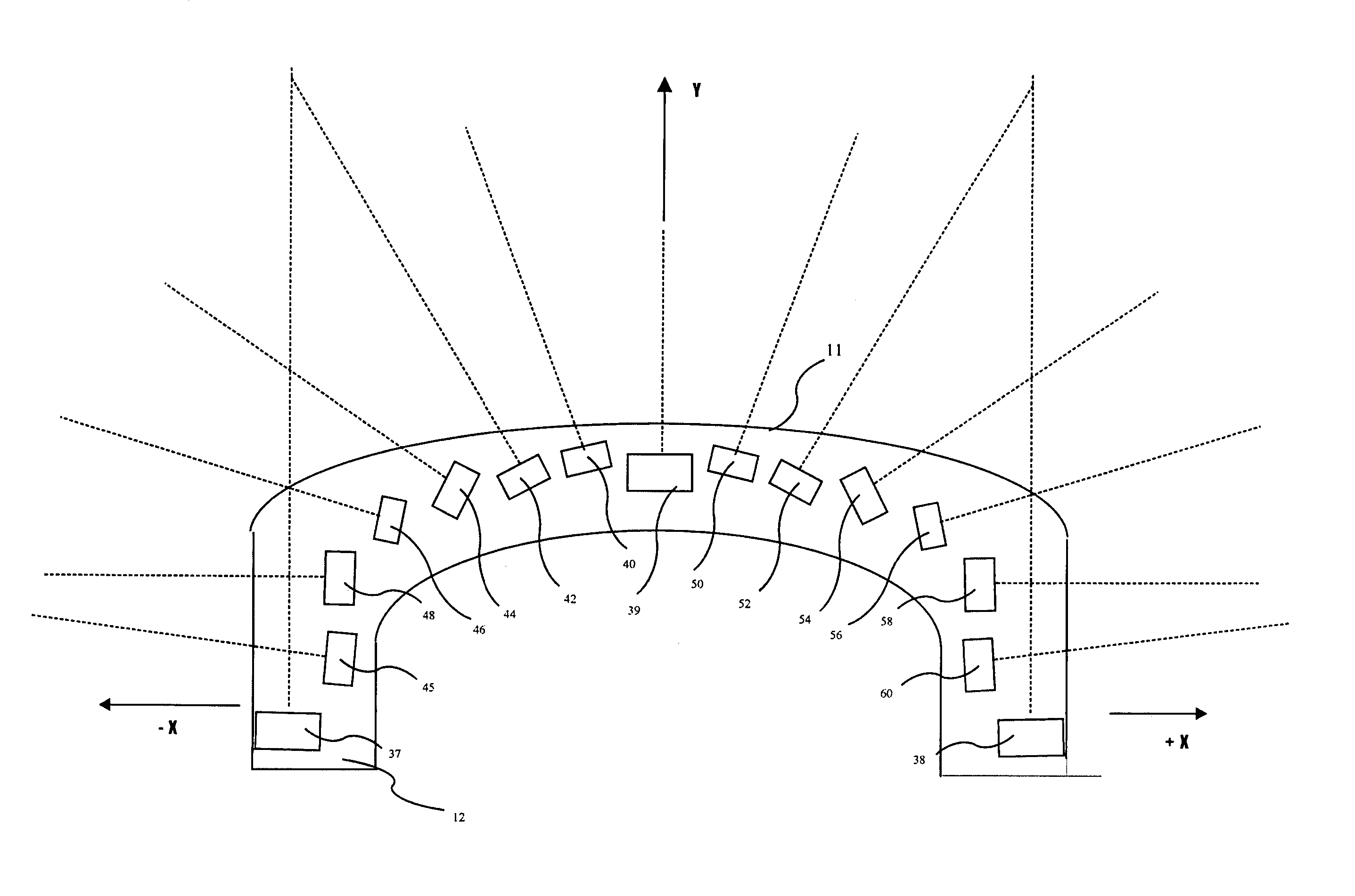
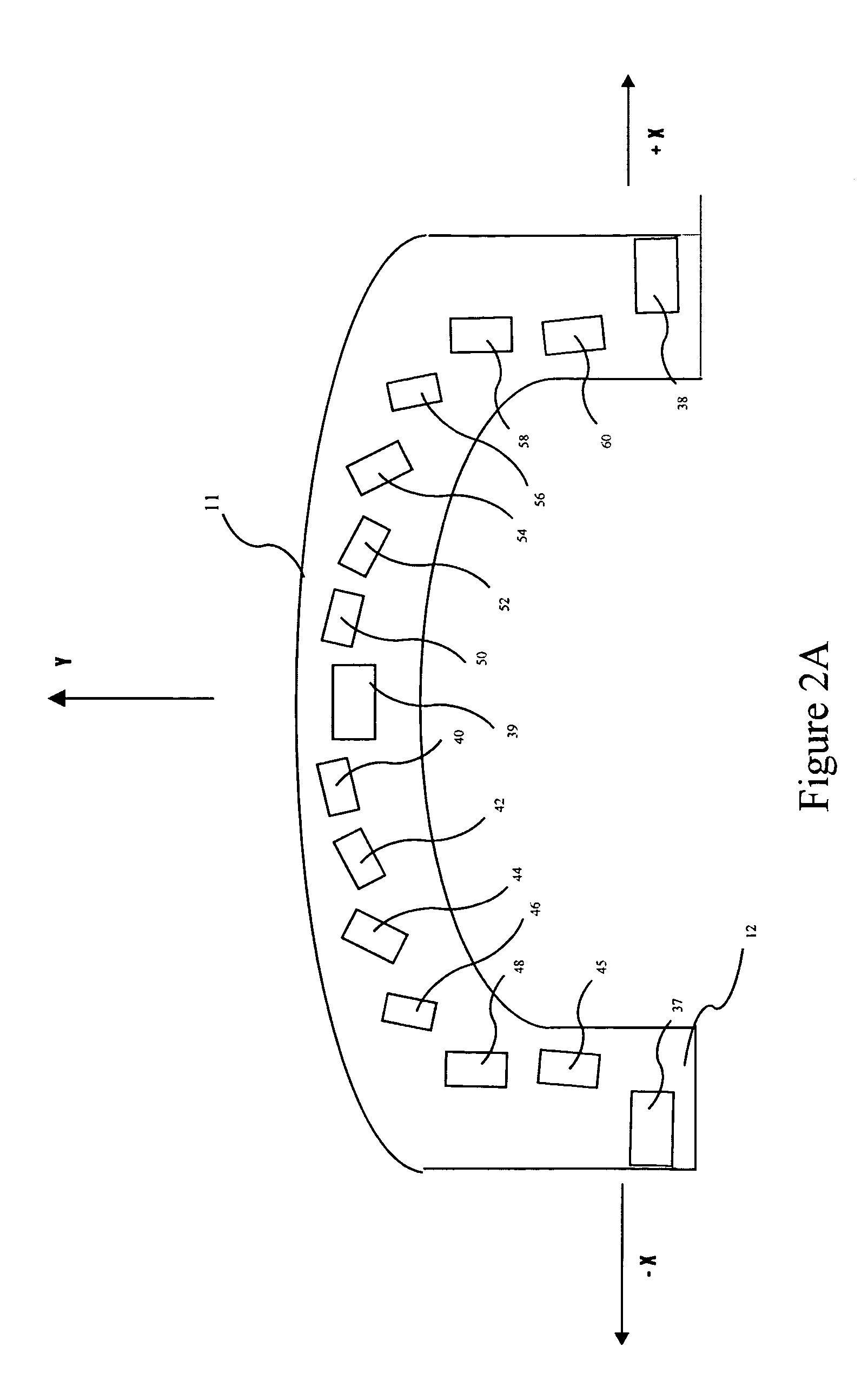
[0024]The present invention provides an improved sensor array for a mobile vehicle. Accordingly, the primary objective is to provide an improved sensor array so that the mobile vehicle detects more accurately the location of objects ahead of the mobile vehicle. In particular, the primary objective of the present invention is to provide a mobile vehicle traveling in a forward direction having a front, a first side, a second side, and a centerline with improved detection ability of objects ahead of the mobile vehicle.

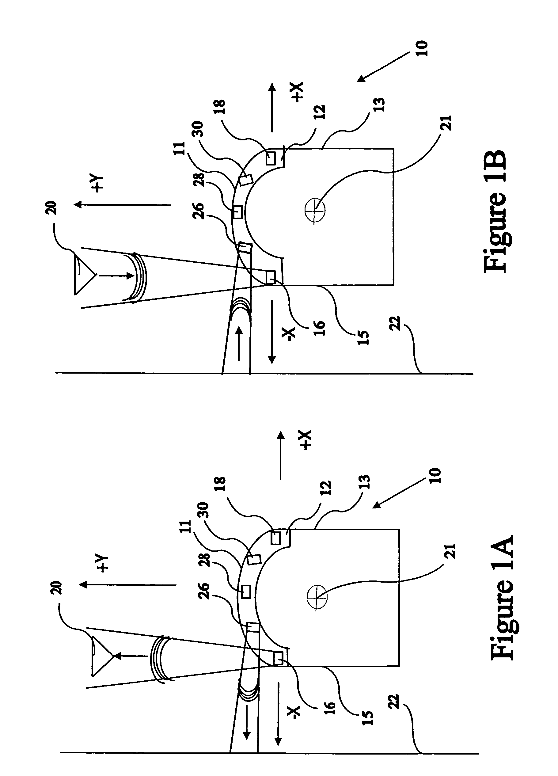
[0025]FIG. 1A is a sensor array mounted on a mobile vehicle 10. The mobile vehicle 10 includes a sensor array 12. In one embodiment of the present invention, mobile vehicle 10 is an unmanned cleaning machine or semiautomatic machine which will follow a programmed path with a minimum or no human supervision. The vehicle 10 generally travels in a forward direction along a vehicle centerline Y parallel to a vehicle velocity vector, and has a first side 15, an a second side 1...


PUM


Abstract

An improved sensor array for a mobile vehicle. The vehicle includes a centerline parallel to a vehicle velocity vector. The sensor array comprises a first sensor mounted to the mobile vehicle at a maximum lateral distance from the centerline near a first side of mobile vehicle and a second sensor mounted to the mobile vehicle at a maximum lateral distance from the centerline near a second side of the vehicle opposite the first side. The first sensor transmits a forward pointing first beam and the second sensor transmits a forward pointing second beam, both beams for detecting an object in the path of the vehicle. A plurality of first oblique beams are pointed to intersect the first beam and a plurality of second oblique beams are pointed to intersect the second beam. The oblique beams, in conjunction with the first and second beams form zones of overlapping beam coverage for better localization of objects in the path of the vehicle.

Description

REFERENCE DOCUMENT[0001]This application is related to the subject matter discussed in Disclosure Document No. 536507 submitted on Aug. 8, 2003, to the Commissioner for Patents entitled “Reconfigurable 195 Degree Sonar Vision with Peripheral Vision.”TECHNICAL FIELD[0002]This invention relates to a sensor array for a mobile vehicle. More particularly, this invention relates to a sensor array for a mobile vehicle, having a first side, a second side opposite the first side, and a centerline parallel to a vehicle velocity vector. The vehicle includes a first sensor mounted on the vehicle at a maximum lateral distance from the centerline and near the first side, the first sensor transmitting a first forward pointing beam. A second sensor is mounted on the vehicle at a maximum lateral distance from the centerline near the second side, and transmits a second forward pointing beam. A first plurality of oblique sensors residing on the vehicle transmit a plurality of first obliquely pointing ...

Claims


Application Information

Patent Timeline
Patent Type & Authority Patents(United States)
IPC IPC(8): G01S15/04G05D1/02G06F7/00
CPCG05D1/0242G05D1/024
Inventor JACOBS, STEVEN
Owner SJ AUTOMATION
Why Eureka
Try Eureka