Optical disk clamping device

a clamping device and optical disk technology, applied in the field of optical disk clamping devices, can solve the problems of deformation or damage of the disk, the clamping device mentioned is unsuitable, and the size of the electronic device is continuously reduced, so as to prevent damage to the optical disk drive or the disk, reduce the clamping force applied to the optical disk, and facilitate the loading and unloading of the disk.

Inactive Publication Date: 2006-05-16
BENQ CORP
View PDF4 Cites 2 Cited by
  • Summary
  • Abstract
  • Description
  • Claims
  • Application Information

AI Technical Summary

Benefits of technology

[0006]An object of the present invention is to provide an optical disk clamping device that solves the above mentioned problem. The optical disk clamping device has a repellent force generated between a diamagnetic member and a magnet when the clamping device rotates so that the repellent force pushes a clamping member to fix an optical disk. The repelling force ceases when the clamping device stops rotating such that the clamping force applied to the optical disk is reduced. Thus, it is easy to load and unload the disk, and damage to the optical disk drive or disk is prevented.
[0008]Due to the structure of the present invention the repellent force is only applied in the axial direction, thus the force neither affects the rotating speed nor the power of the motor. Further, the present invention improves the stability of the motor and the clamping device of the optical disk drive.

Problems solved by technology

As the size of electronic devices is continuously reduced, the mentioned clamping device is unsuitable, especially for thin type optical disk drives.
In practice, using the above mentioned devices, it is difficult to load or unload the disk, and can cause deformation or damage to the disk.
Incorrect application of force on the disk may further damage the motor of the optical disk drive.

Method used


Image

  • Optical disk clamping device
  • Optical disk clamping device
  • Optical disk clamping device

Examples


Embodiment Construction

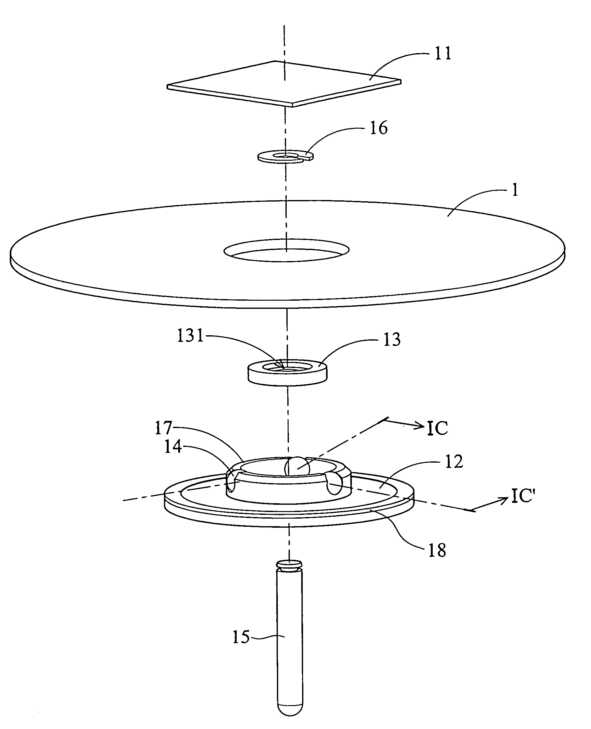
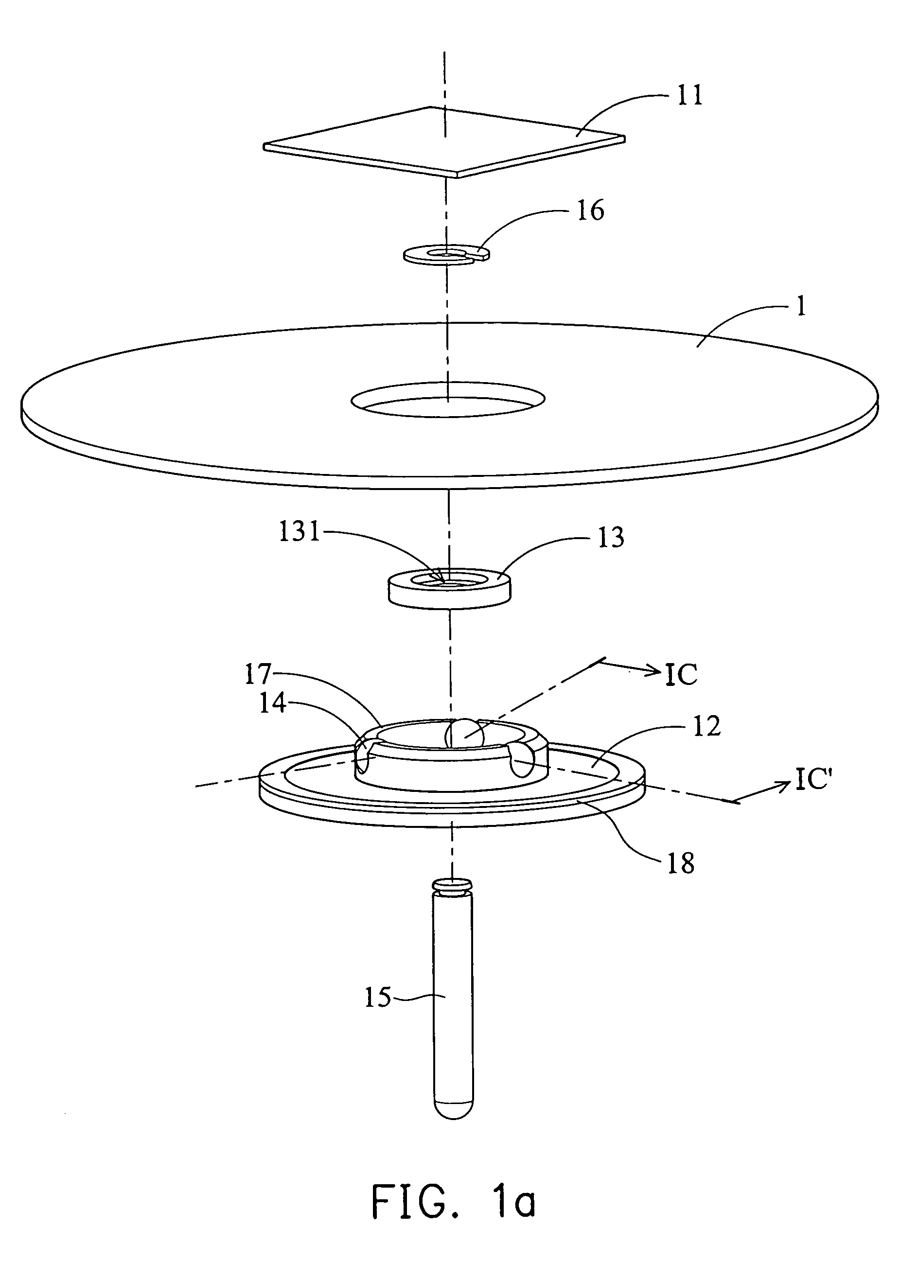
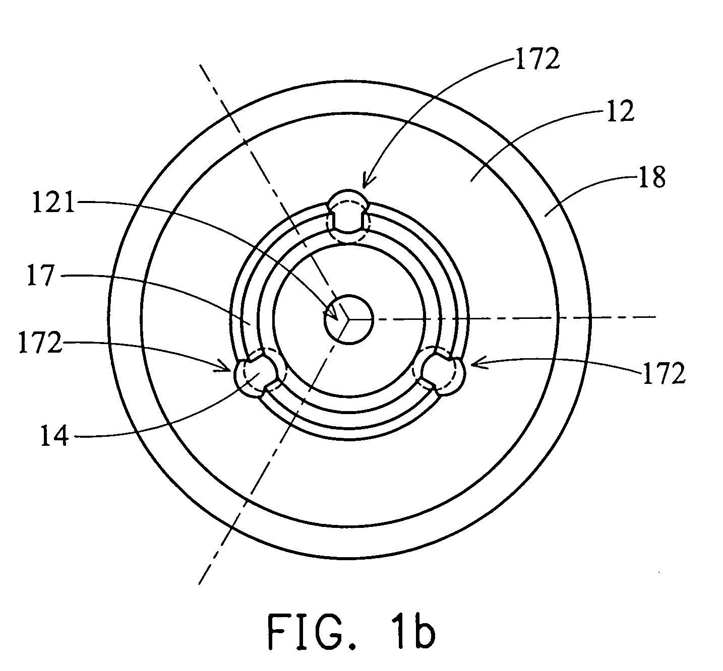
[0017]FIGS. 1a, 1b, 1c, and 1d show an optical disk clamping device including a diamagnetic member 11, a turntable 12, a magnet 13, a clamping member 14, a shaft 15, and a retaining washer 16. In the embodiment, the diamagnetic member 11 is an aluminum member, for example, the diamagnetic member 11 is an aluminum cover of an optical disk drive, and the clamping member 14 is a steel ball. The turntable 12 is disposed in the optical disk drive, and the shaft 15 is fastened to the turntable 12. The shaft 15 is rotated by a motor in the optical disk drive such that the turntable 12 rotates with the shaft 15.

[0018]The turntable 12 supports an optical disk 1. The magnet 13 is disposed between the diamagnetic member 11 and the turntable 12. The clamping member 14 is disposed on the turntable 12 to support the magnet 13. The turntable 12 defines a positioning portion 17 to restrain and support the clamping member 14. The center of the magnet 13 defines a first opening 131 and the center of ...


PUM


Abstract

An optical disk clamping device. The device includes a diamagnetic member, a turntable, a magnet, and a clamping member. The turntable supports an optical disk. The magnet is disposed between the diamagnetic member and the turntable. The clamping member is disposed on the turntable to support the magnet. A repellent force is generated between the diamagnetic member and the magnet when the turntable rotates, pushing the magnet toward the clamping member to fix the optical disk.

Description

BACKGROUND OF THE INVENTION[0001]1. Field of the Invention[0002]The present invention relates to an optical disk clamping device. In particular, the present invention relates to an optical disk clamping device in which an optical disk can be easily loaded and unloaded.[0003]2. Description of the Prior Art[0004]Currently, the optical disk clamping devices of the optical disk drives used in desktop computers are magnets which attract or repel a disk from the turntable. As the size of electronic devices is continuously reduced, the mentioned clamping device is unsuitable, especially for thin type optical disk drives. Thus, another rotatable locking hub with a plurality of retractable retaining prongs is required for DVD players or thin type optical disk drives.[0005]In practice, using the above mentioned devices, it is difficult to load or unload the disk, and can cause deformation or damage to the disk. Incorrect application of force on the disk may further damage the motor of the opt...

Claims


Application Information

Patent Timeline
IPC IPC(8): G11B25/04G11B17/028
CPCG11B17/0282
Inventor LIN, TUNG-LUNGLIU, CHIH-TSUNG
Owner BENQ CORP
Why Eureka
Try Eureka