Straw-filling device

Inactive Publication Date: 2006-05-23
HAMILTON KATHRYN M
View PDF27 Cites 19 Cited by
  • Summary
  • Abstract
  • Description
  • Claims
  • Application Information

AI Technical Summary

Benefits of technology

[0014]In one embodiment of the present invention, after falling through the chutes, the straw comes to rest in the capture area, where it is pinched and sealed at the bottom in preparation for filling. A filling nozzle moves into a predefined position over the straw and the straw is filled with a preset amount of liquid. After filling, the top of the straw is pinched

Problems solved by technology

However, these devices generally share one or more disadvantages, including large size, lack of portability, high complexity, high cost and/or lack of commercial availability, lack of adaptability to different types and sizes of products, and/or an inability to process small batches efficiently.
Many of these disadvantages are particularly apparent when the devices are needed in a retail-type setting for producing only a small quantity of filled straws at one time, such as is often encountered in small farm-based or single store-type businesses.
It requires a fairly large supply of liquid and straws to operate, appears to be fairly complex to assemble, operate, and clean, and therefore cannot be easily or efficiently used to produce a small batch of fi

Method used


Image

  • Straw-filling device
  • Straw-filling device
  • Straw-filling device

Examples


Example

[0025]The present invention is an automated, fully programmable, and adaptable device for filling straws or straw-like receptacles with any type of flowing, or flowable, liquid. The device of the present invention is portable, affordable, and highly adjustable. The present invention may be effectively utilized in many industries including, but not limited to, beekeeping (honey producing), maple syrup producing, coffee / tea, candy / food, medical, and industrial.

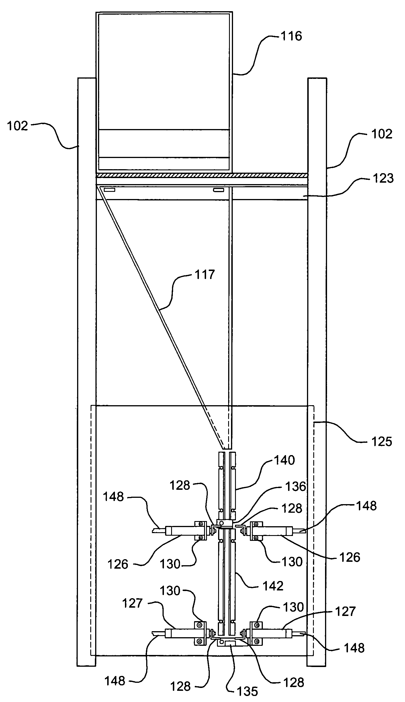
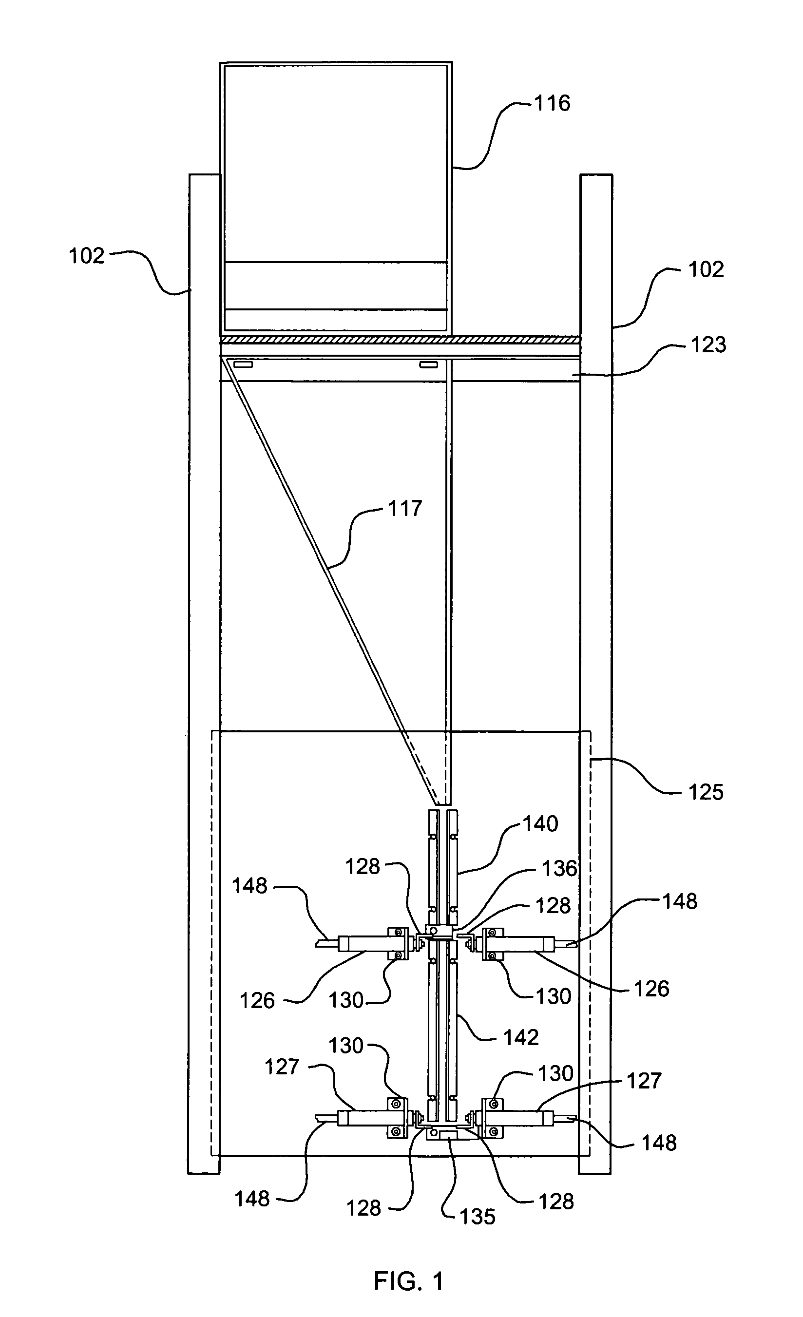
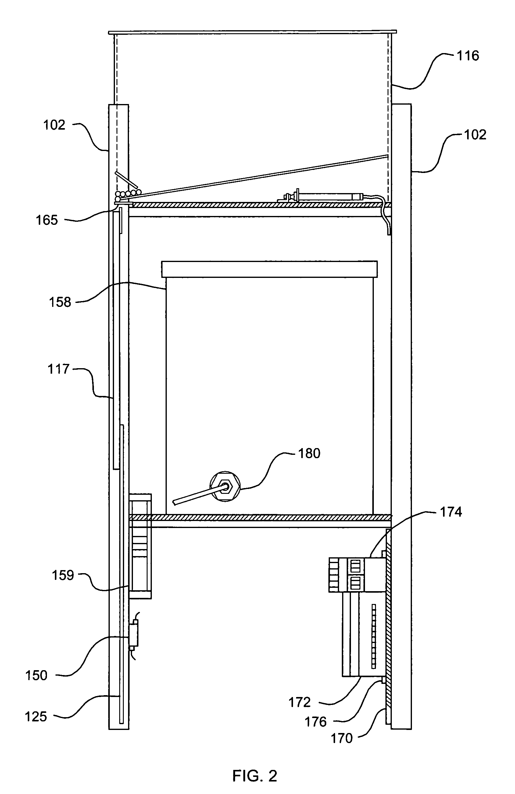
[0026]In an embodiment of the present invention, a straw or straw-like package is dropped from a hopper down one or more chutes into a capture area. The straw is then captured, held, and filled with a free flowing liquid, after which it is sealed. The straw dropping, capture, filling, and sealing actions are preferably automatically controlled via a pre-programmed electric sequence. The device also preferably automatically warms the fill liquid and switches itself off when the fill liquid is gone or the straw hopper is empty. Th...


PUM

PropertyMeasurementUnit
Timeaaaaaaaaaa
Flow rateaaaaaaaaaa
Areaaaaaaaaaaa

Abstract

An automated, fully programmable, and adaptable device fills straws or straw-like packages with any type of flowing, or flowable, liquid. A straw is dropped from a hopper down chutes into a capture area where it is held and filled with liquid, after which it is sealed. The straw dropping, capture, filling, and sealing actions are preferably automatically controlled by a preprogrammed electronic controller. The major elements of a typical embodiment of the invention include means for dropping a straw or other receptacle into a fixed mounting position consistently, optional means for heating fluids throughout the fill process, means for filling the receptacle, and means for sealing the receptacle. The straw hopper has a retractable slide plate at its base that slides back to allow only one straw at a time to fall through the chutes into the capture area. In the preferred embodiment, the slide plate at the bottom of the hopper moves back and forth in a predefined fully programmable sequence. In one embodiment, when the straw comes to rest in the capture area, it is pinched and sealed at the bottom in preparation for filling. A filling nozzle moves into a predefined position over the straw to be filled and the straw is filled with a preset amount of liquid. After filling, the top of the straw is pinched and then sealed, completing packaging of the liquid. Preferably, the sequence of actions may be easily adapted or changed by reprogramming the automatic controller. After sealing, the straw is dropped into the collection area. Preferably, steps are monitored by one or more sensor monitors, preferably with one sensor monitoring each of the three phases of operation.

Description

[0001]This application claims priority to U.S. Provisional Application Ser. No. 60 / 402,159, filed Aug. 8, 2002.FIELD OF THE INVENTION[0002]This invention relates to packaging devices and, in particular, to devices for filling straw-like receptacles with liquids.BACKGROUND[0003]A large number of devices for filling straws and other straw-like or pillow-type packages with liquids are known in the art. However, these devices generally share one or more disadvantages, including large size, lack of portability, high complexity, high cost and / or lack of commercial availability, lack of adaptability to different types and sizes of products, and / or an inability to process small batches efficiently. Many of these disadvantages are particularly apparent when the devices are needed in a retail-type setting for producing only a small quantity of filled straws at one time, such as is often encountered in small farm-based or single store-type businesses. A good example of such an application is t...

Claims


Application Information

Patent Timeline
IPC IPC(8): B65B1/04B65B3/16B65B57/06
CPCB65B57/06B65B3/16
Inventor HAMILTON, KATHRYN M.
Owner HAMILTON KATHRYN M
Why Eureka
Try Eureka