
Pipe bending apparatus

a technology of pipe bending and pipe wall, which is applied in the field of pipe bending apparatus, can solve the problems of inability to provide a simple and practical pipe bending system, inability to meet the needs of pipe sections, and crushing of pipe walls,

Inactive Publication Date: 2006-05-23
THEENER RONALD E
View PDF14 Cites 16 Cited by
  • Summary
  • Abstract
  • Description
  • Claims
  • Application Information

AI Technical Summary

Benefits of technology

[0006]An object of the present invention is a pipe bending apparatus consistently providing successful bends wherein ovality of the pipe cross-section is maintained. A related object of the invention is a pipe bending apparatus avoiding the collapsing of the pipe walls during the bending operation.

Problems solved by technology

While all of the aforementioned prior art constructions present improvements for pipe bending machinery, they are uniformly deficient with respect to their failure to provide a simple and practical pipe bending system for consistently maintaining ovality of a pipe during the bending process.
As most individuals who operate pipe bending machines are all too well aware, uneven application of the bending pressure on a length of pipe most often results in the collapse or crushing of the pipe walls in the vicinity of the bend, thereby rendering that particular pipe section useless.
Not only is this a waste of materials, the operators' time is also wasted, both causing the pipe bending process to be unnecessarily expensive.

Method used


Image

  • Pipe bending apparatus
  • Pipe bending apparatus
  • Pipe bending apparatus

Examples


Embodiment Construction

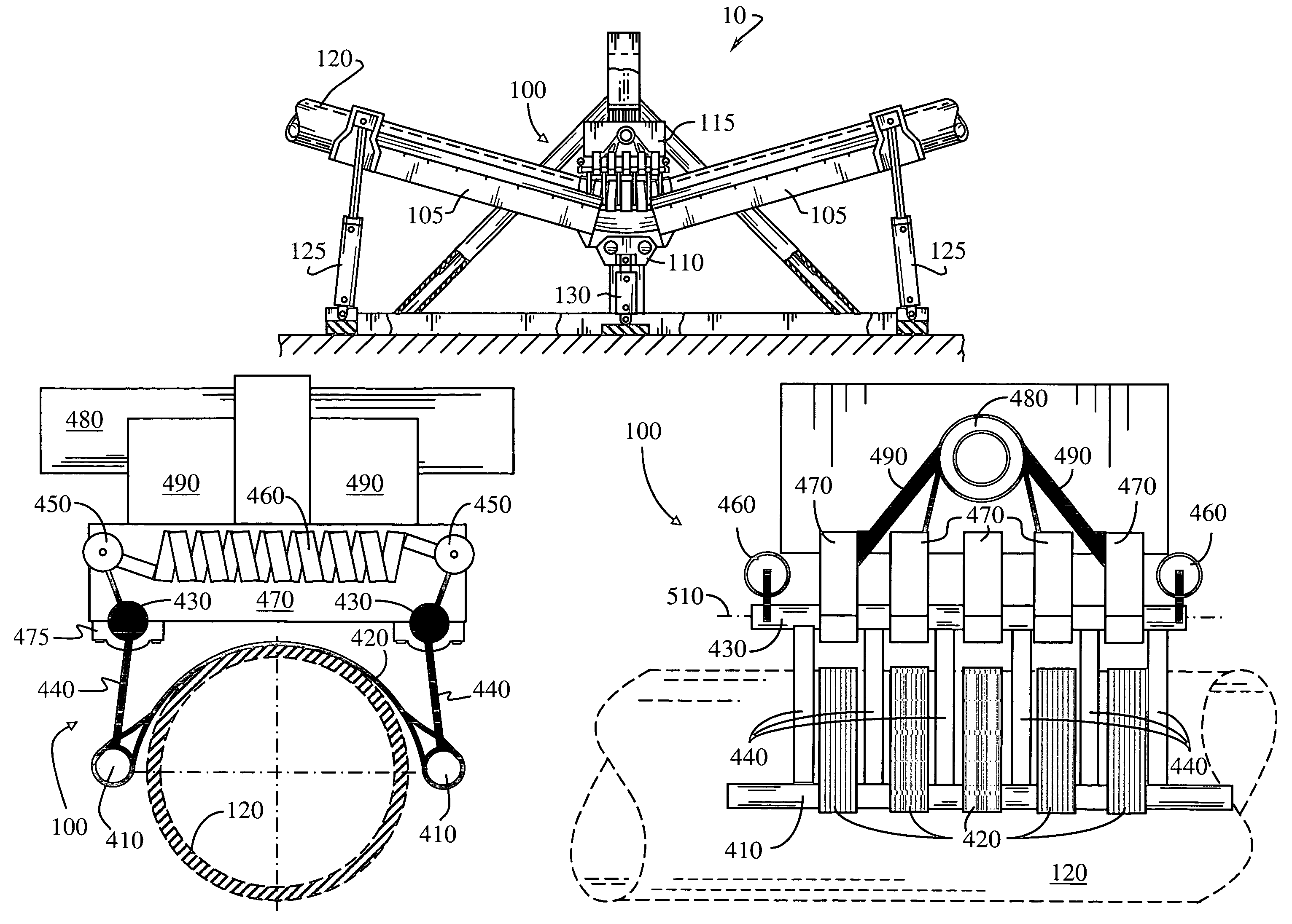
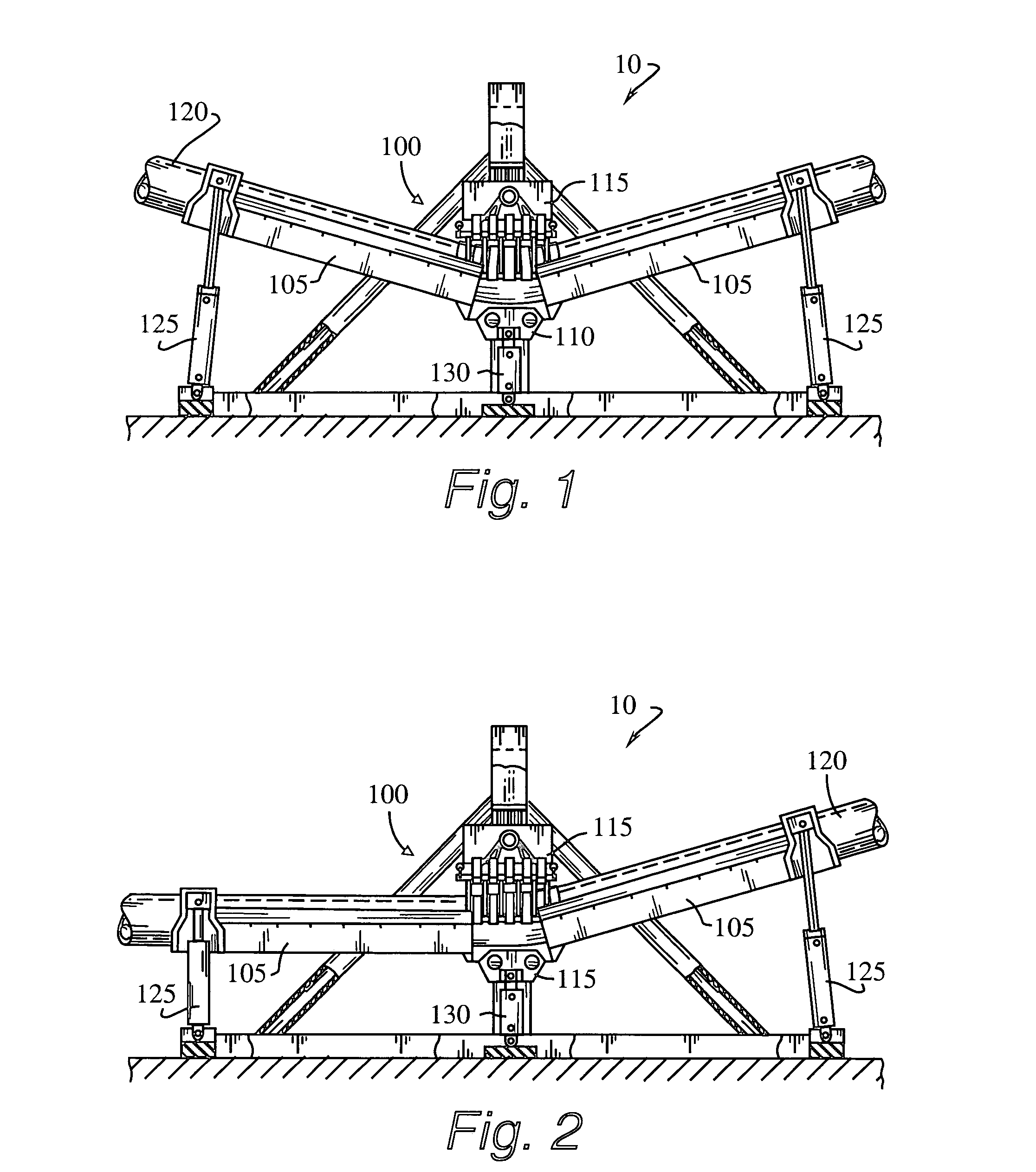
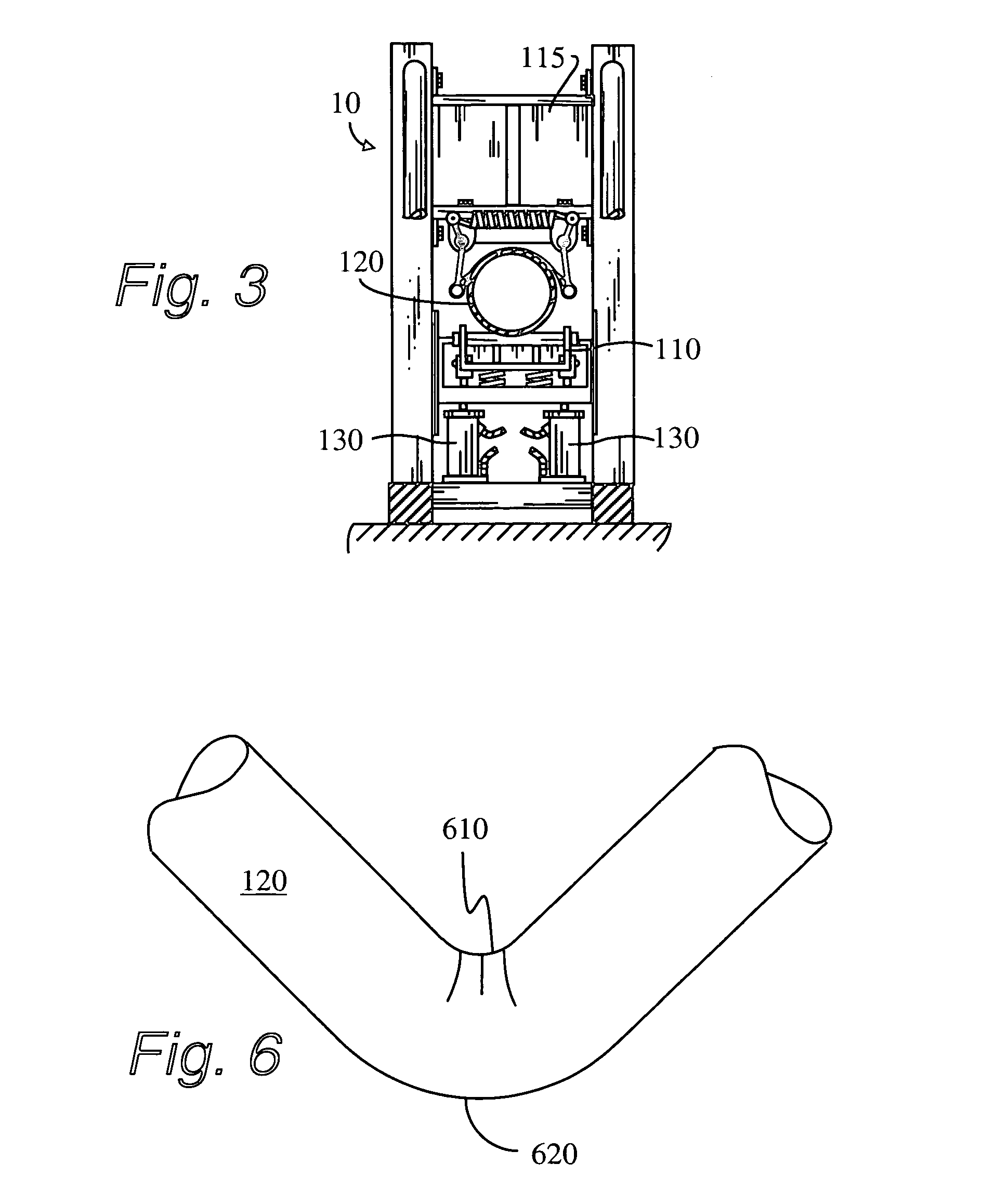
[0015]As shown in FIGS. 1–3, the pipe bending apparatus is designated generally as 10 and includes a pair of elongated bed members 105 whose inboard ends are pivotally connected to a floating hinge plate 110 which cooperates with a pin up plate 115 which holds the top pipe die for captively engaging a section of pipe 120 such that the relative movement between the hinge plate 110, the pin up plate 115, and the bed members 105 will produce a selected bend or curvature in the section of pipe 120 at the juncture of the hinge plate 110 and the pin up plate 115.

[0016]Referring mainly to FIGS. 1–2, it can be seen that the outboard end of the bed members 105 are operatively associated with the bending bed hydraulic ram units 125, the hinge plate 110 is operatively associated with the hinge plate hydraulic ram unit 130.

[0017]A harness assembly 100 is also seen in FIGS. 1–3, but is shown in detail in FIGS. 4 and 5. The harness assembly includes a framework comprising a pair of lower members ...


PUM


Abstract

An improved pipe bending apparatus comprising a plurality of belts supporting the minor radius of the bend. The belts cannot support stresses sufficient to allow concentrated stress to cause the pipe walls to collapse. The belts are affixed to a framework that forces the belts into the sides of the pipe, thereby providing support to maintain ovality of the pipe cross-section.

Description

DESCRIPTION OF RELATED ART[0001]This application is an improvement over U.S. Pat. No. 5,884,519 which issued on Oct. 11, 1994 and is entitled “Articulated Three Point Bending Apparatus”, the content of which is incorporated herein by reference.[0002]As can be seen by reference to the following U.S. Pat. Nos. 2,938,564; 3,934,450; 4,331,018; and 5,237,847, the prior art is replete with myriad and diverse pipe bending apparatuses.[0003]While all of the aforementioned prior art constructions present improvements for pipe bending machinery, they are uniformly deficient with respect to their failure to provide a simple and practical pipe bending system for consistently maintaining ovality of a pipe during the bending process.[0004]As most individuals who operate pipe bending machines are all too well aware, uneven application of the bending pressure on a length of pipe most often results in the collapse or crushing of the pipe walls in the vicinity of the bend, thereby rendering that par...

Claims


Application Information

Patent Timeline
IPC IPC(8): B21D3/10B21D9/08
CPCB21D9/08
Inventor THEENER, RONALD E.
Owner THEENER RONALD E
Learn More