Pressure control architecture for fluid tanks having fluid level sensing

a technology of pressure control and fluid level sensing, which is applied in the field of fluid tanks, can solve the problems of frequent re-increasing system, low fluid level, and high cost of umbilical systems, and achieve the effects of reducing fluid impedance, reducing fluid leakage, and improving fluid usage and efficiency

Inactive Publication Date: 2006-05-23
FUJIFILM BUSINESS INNOVATION CORP
View PDF2 Cites 4 Cited by
  • Summary
  • Abstract
  • Description
  • Claims
  • Application Information

AI Technical Summary

Benefits of technology

[0013]This invention is directed to a fluid tank, such as for use in a printing device and which has a foam element inside of a fluid tank chamber which has a fluid tank supply port opening. Variation in the compression of the foam element results in reduced fluid leakage from the fluid tank through the fluid tank supply opening when the supply opening seal is removed, improved fluid usage and efficiency, reduced fluid impedance within the foam element during the process of filling the tank with fluid, reduced fluid leakage at high altitude / reduced atmospheric pressure, reduction of deprime conditions, and improved fluid delivery pressure to the print head to which the fluid tank is connected in operation.

Problems solved by technology

Replacing cartridges requires frequent interaction by the user, and is considered disadvantageous for fluid ejectors used in volume production or connected by a network to the ejection data source.
Umbilical systems can be expensive, requiring pressurization, tubing, tube harness dressing, and can suffer performance degradation from moisture loss, pressure fluctuations due to acceleration or temperature variation, and motion hysterisis from tubing harness drag.
In an ink jet printer, periodic refill systems commonly do not accurately meter the ink that is deposited into the printhead.
Consequently, this under-filling wastes space and reduces the productivity of the printer due to the greater frequency of refill operations.
Fluid level sensing in fluid container in these technologies is difficult because electrical fluid sensing may introduce hazards, e.g., spark ignition into the fluid contained in the fluid container, or in which the fluid may deteriorate the electrical sensors, e.g., from corrosion.

Method used


Image

  • Pressure control architecture for fluid tanks having fluid level sensing
  • Pressure control architecture for fluid tanks having fluid level sensing
  • Pressure control architecture for fluid tanks having fluid level sensing

Examples


Embodiment Construction

[0029]The following detailed description of various exemplary embodiments of the fluid containers having a communication channel between the manifold and ink reservoir, according to this invention may refer to one specific type of fluid system, e.g., an ink jet printer that uses the refillable fluid containers according to this invention, for sake of clarity and familiarity. However, it should be appreciated that the principles of this invention, as outlined and / or discussed below, can be equally applied to any known or later-developed fluid ejection systems, beyond the ink jet printer specifically discussed herein.

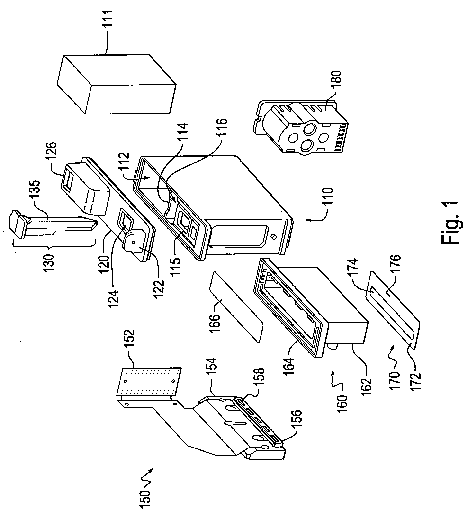
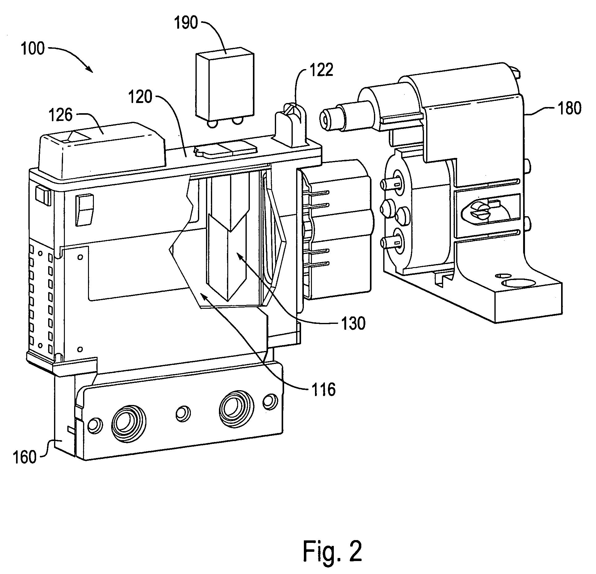
[0030]FIG. 1 shows an isometric exploded view of a cartridge reservoir 100 for an inkjet printhead. The cartridge reservoir 100 includes a fluid chamber 110, a chamber lid 120, a fluid ejection interface module 150, a manifold 160, a face tape 170 and a refill port 180. Such conventional refillable fluid containers may optionally include a fluid level sensor 130, such as ...


PUM


Abstract

A refillable fluid container system having a pressure control architecture in which persistent air bubbles are released from a capillary or foam fluid reservoir and are directed from an optical level sensing system in a liquid fluid reservoir.

Description

BACKGROUND OF THE INVENTION[0001]1. Field of Invention[0002]This invention relates to fluid tanks.[0003]2. Description of Related Art[0004]Fluid ejector systems, such as drop-on-demand liquid ink printers, have at least one fluid ejector from which droplets of fluid are ejected towards a receiving sheet. Scanning ink jet printers are equipped with fluid ejection heads containing fluid ink. The ink is applied to a sheet in an arrangement based on print data received from a computer, scanner or similar device. To control the delivery of the fluid to the sheet, fluid ejection heads are moved across the sheet to provide the fluid to the sheet, which is ejected as drops. These drops correspond to a liquid volume designated as pixels. Each pixel is related to a quantity needed to darken or cover a particular unit area.[0005]In order to lower cost and improve performance by limiting inertia, moving-head fluid ejection systems are designed with low weight fluid ejection heads that often use...

Claims


Application Information

Patent Timeline
Patent Type & Authority Patents(United States)
IPC IPC(8): B41J2/175B41J2/195B05C5/00
CPCB41J2/17513
Inventor HILTON, BRIAN S.MERZ, ERIC A.
Owner FUJIFILM BUSINESS INNOVATION CORP
Why Eureka
Try Eureka