Miniature LED flashlight

a flashlight and led light technology, applied in the field of flashlights, can solve the problems of large overall size of the flashlight structure, difficult assembly of the carabiner type device, and less flexibility of the key ring flashlight type than the chain type, and achieve the effect of simple and elegan

Active Publication Date: 2006-05-23
PRINCETON TECTONICS
View PDF3 Cites 13 Cited by
  • Summary
  • Abstract
  • Description
  • Claims
  • Application Information

AI Technical Summary

Benefits of technology

[0011]This invention provides a simple and elegant solution to the problem of temporarily removing a miniature flashlight from a keyring or other article to which it is normally attached. The user can readily separate the flashlight from its mounting clip without fumbling with a snap hook in the dark. Yet, the flashlight otherwise remains securely engaged with the mounting clip.

Problems solved by technology

However, the carabiner type key ring flashlight is somewhat less flexible than the chain type.
Thus, in using a carabiner type key ring flashlight to illuminate a door lock at night, it is often necessary to remove the flashlight from the key ring, since often the key cannot be inserted into the lock while the light is directed at the lock.
The carabiner type flashlight can be readily removed from the key ring, but in order to make easy removal in the dark possible, the structure of the carabiner type snap hook is necessarily somewhat bulky, making the overall size of the flashlight structure large and unwieldy.
Moreover, the assembly of the carabiner type device is somewhat difficult because it entails the installation of a spring needed to urge the movable element of the snap hook toward its closed condition.

Method used


Image

  • Miniature LED flashlight
  • Miniature LED flashlight
  • Miniature LED flashlight

Examples


Embodiment Construction

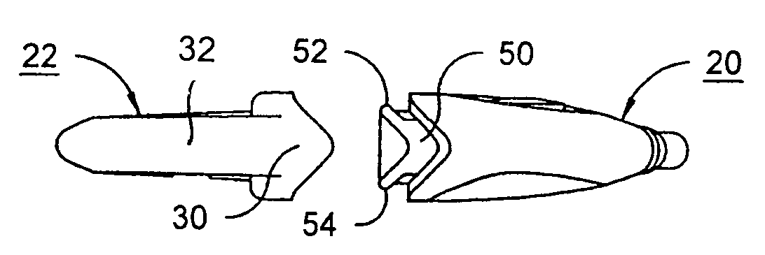
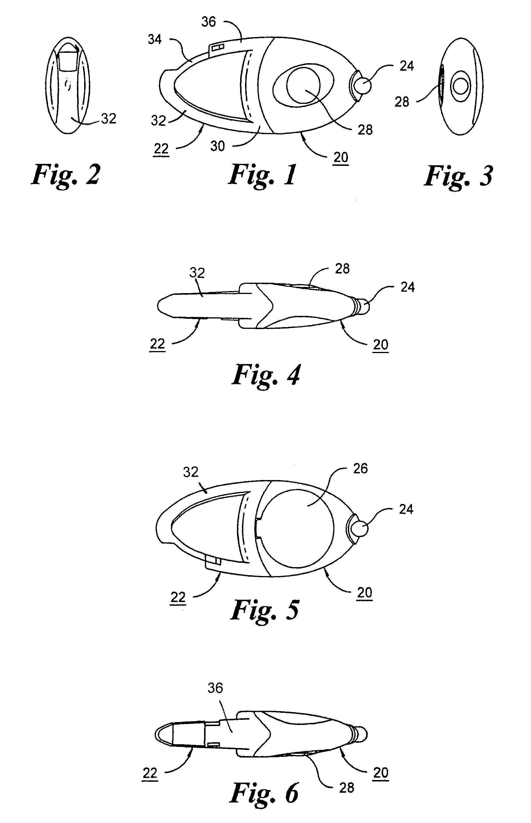
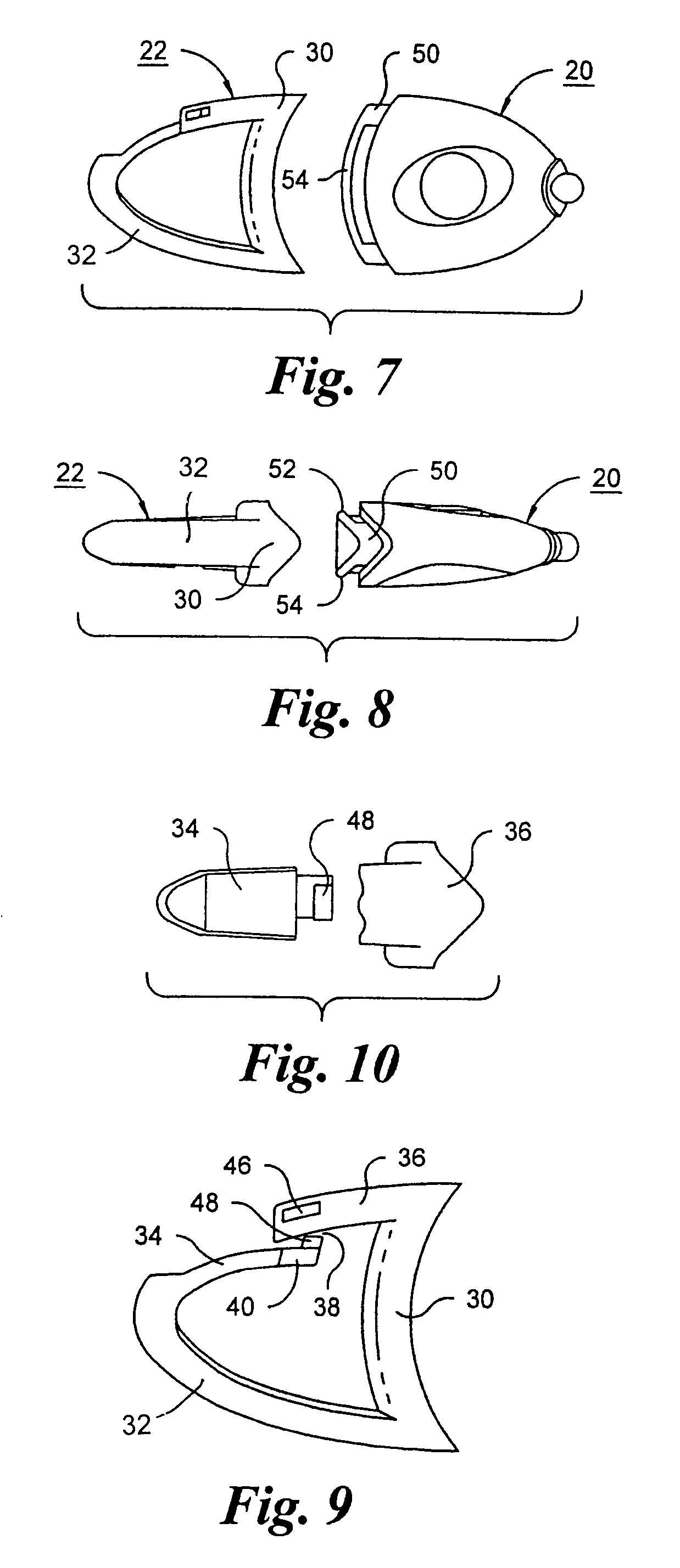
[0029]As seen in FIGS. 1–6, the miniature flashlight is composed of two principal parts, a flashlight assembly 20, and an attachment loop 22.

[0030]The flashlight assembly includes a high intensity light-emitting diode (LED) device 24, which includes a lens for focusing light emitted by the LED into a narrow beam directed along the direction of elongation of the flashlight assembly as seen in FIGS. 1, and 4–6. On the rear of the flashlight assembly 20, as shown in FIG. 5, a removable cover 26 encloses an interior space for receiving a power supply, preferably consisting of a pair of coin cells (not shown). A push-button 28, seen in FIGS. 1, 3, 4, and 6, is used to control an electrical switch (not shown) provided inside the flashlight assembly. The switch can be a simple momentary two-contact switch connected directly to the LED and the power supply so that the LED can be turned on while the button 28 is depressed and is otherwise turned off. Preferably, however, the push-button 28 c...


PUM


Abstract

A miniature LED flashlight is composed of a flashlight assembly and an attachment loop. The attachment loop is configured to require a two-step manipulation for attachment or detachment from a key ring. The flashlight assembly and attachment loop are attached by a snap fit relationship between a projection on one and a recess on the other, and can be readily disconnected by application of a bending force.

Description

CROSS REFERENCE TO RELATED APPLICATION[0001]This application claims the benefit of provisional application No. 60 / 493,306, filed Aug. 7, 2003.FIELD OF THE INVENTION[0002]This invention relates to flashlights, and more particularly to an improved miniature LED flashlight suitable for attachment to a keychain or the like.BACKGROUND OF THE INVENTION[0003]Keychain flashlights have been known for a long time, and became increasingly popular with the introduction of high-efficiency light emitting diode (LED) bulbs. LED bulbs can be powered by one or more “coin” cells, and can emit a high intensity beam of light. Depending on the particular LED used, an LED keychain flashlight can emit light in any of a variety of colors, such as white, red, blue and green.[0004]These miniature flashlights are typically designed so that they can be removably attached to a key ring. Some have a case containing the power source, the LED and a switch, and a chain connecting the case to a snap hook which can r...

Claims


Application Information

Patent Timeline
Patent Type & Authority Patents(United States)
IPC IPC(8): F21L4/04A44B15/00F21L4/02F21V21/088
CPCA44B15/005F21L4/027F21V21/0885Y10S362/80F21Y2101/02F21Y2115/10
Inventor KUMTHAMPINIJ, YOSZOROVICH, KENNETH
Owner PRINCETON TECTONICS
Why Eureka
Try Eureka