Rail system for distributing power and data signals

a technology of power and data signals and rails, applied in the direction of gaseous cathodes, electrical apparatus casings/cabinets/drawers, coupling device connections, etc., can solve the problems of large number of wires and cables, complex distribution systems employed in large commercial and industrial operations, and high cost and time-consuming tasks

Inactive Publication Date: 2006-05-23
ROCKWELL AUTOMATION TECH
View PDF8 Cites 38 Cited by
  • Summary
  • Abstract
  • Description
  • Claims
  • Application Information

AI Technical Summary

Problems solved by technology

Distribution systems employed in large commercial and industrial operations can be complex.
Connecting a large number of wires and cables can be a costly and time consuming task.

Method used


Image

  • Rail system for distributing power and data signals
  • Rail system for distributing power and data signals
  • Rail system for distributing power and data signals

Examples


Embodiment Construction

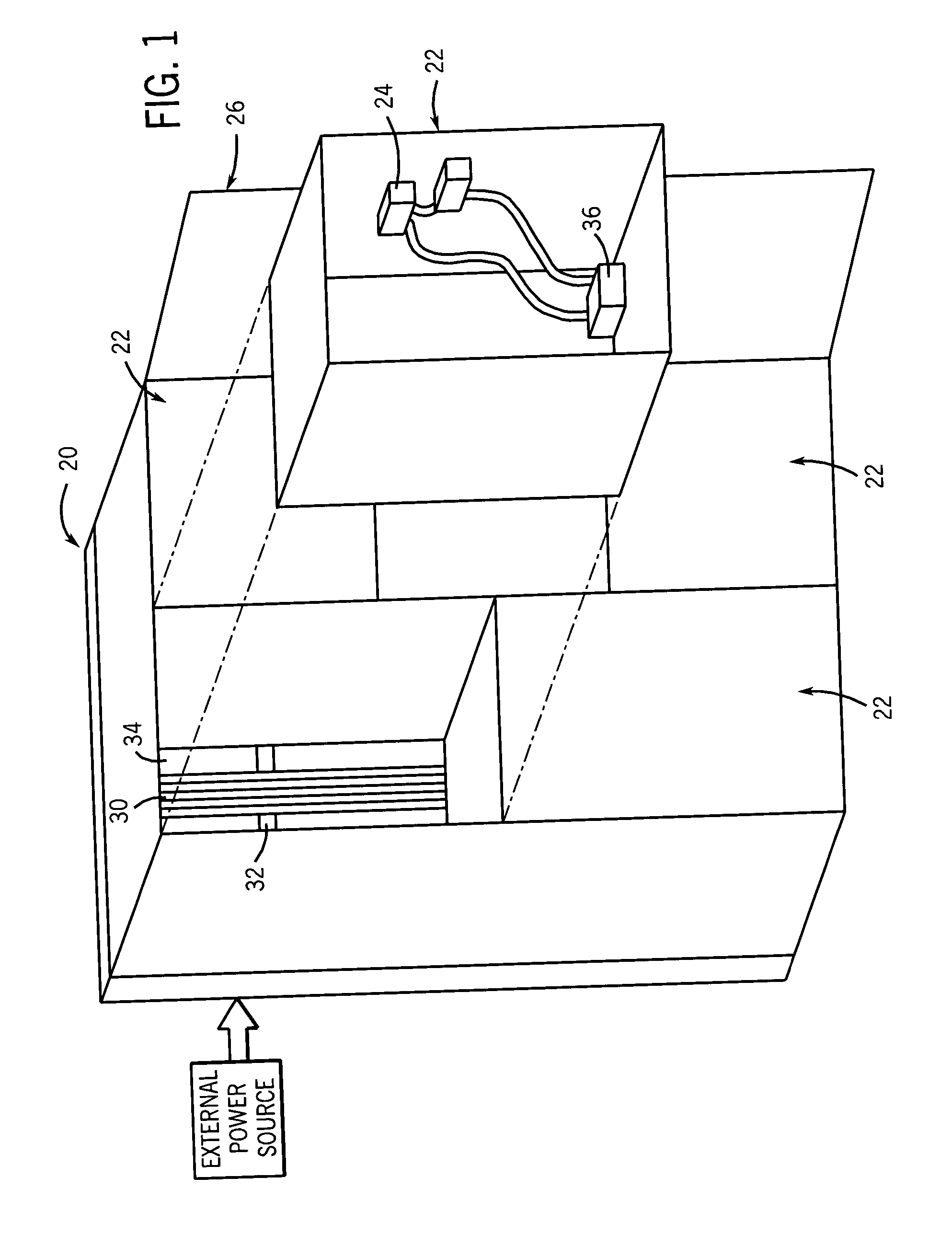
[0021]FIG. 1 illustrates an exemplary enclosure 20. It is to be noted that the present technique may be employed as a connection system in various types of electrical assemblies where power and data transmission are desired. However, for the purposes of explanation, the present technique will be described in relation to a power and data connection within an enclosure. The enclosure 20 has one or more doors 26 such that the doors can be closed to isolate the components housed within component assemblies 22 while in operation and opened to access the components when necessary. Inside the enclosure 20 may be a collection of removable component assemblies 22 having a set of components 24. These components 24 are generally interconnected as they send and receive various signals to one another and to external circuitry.

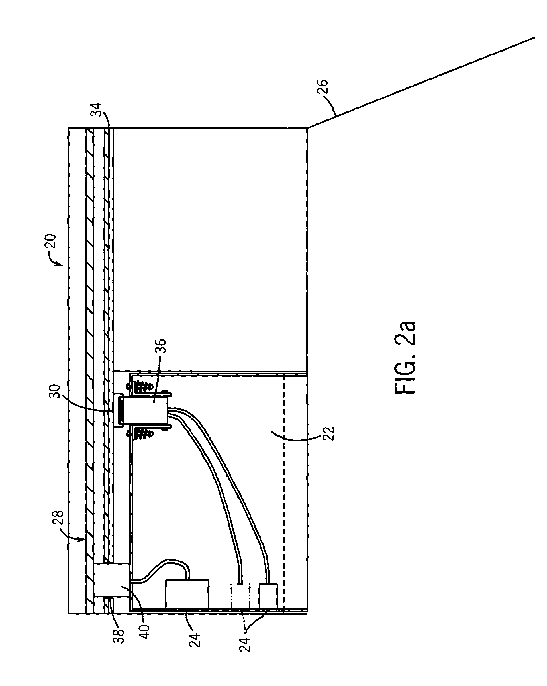
[0022]The exemplary enclosure 20 receives a first power level from a bus 28 (shown in FIG. 2). This bus 28 may carry main power, for example, 3 phase ac power, such as 208 ...


PUM


Abstract

Transmission of electrical signals can be conducted over a rail. The rail, which may be an at least partially open rail structure, may be disposed within an enclosure, and can be used to transmit data and power signals to an assembly of electrical components. A connector assembly may also be provided to facilitate the transmission of data and power signals between the components and the rail.

Description

FIELD OF THE INVENTION[0001]The present technique relates to the field of distributing data and power signals. More particularly, the invention relates to a rail system that feeds data and power signals to various components.BACKGROUND OF THE INVENTION[0002]Distribution systems employed in large commercial and industrial operations can be complex. Motor control centers (MCC), for example, are used in these operations to manage both internal and external power as well as data communication. Within the MCC are disposed a variety of components or devices used in the operation to control various machines or motors. Typically, the MCC is connected to a main power line that feeds 3-phase ac power, such as 208 to 690 Volts ac power, into the MCC. The MCC then manages and distributes this power to various components within the assembly and operation. Exemplary devices contained within the MCC are motor starters, overload relays, or circuit breakers. These devices are then affixed within var...

Claims


Application Information

Patent Timeline
Patent Type & Authority Patents(United States)
IPC IPC(8): H02G3/18H02B11/12
CPCH02B11/12
Inventor BRANDT, DAVID D.SHEN, JIEJENSEN, DAVID L.
Owner ROCKWELL AUTOMATION TECH
Why Eureka
Try Eureka