Communication wire

a technology of communication wires and wires, applied in the field of wires, can solve problems such as transmission errors or data loss, delay skew problems can become increasingly magnified, and the signal cannot be properly reassembled

Inactive Publication Date: 2006-05-23
COMMSCOPE TECH LLC
View PDF62 Cites 41 Cited by
  • Summary
  • Abstract
  • Description
  • Claims
  • Application Information

AI Technical Summary

Problems solved by technology

First, there is the twist of the wires that make up the twisted pair.
Measured in nanoseconds, the timing difference in signal transmissions between the twisted wire pairs within a cable in response to a generated signal is commonly referred to as “delay skew.” Problems arise when the delay skew of the signal transmitted by one twisted pair and another is too large and the device receiving the signal is not able to properly reassemble the signal.
Such a delay skew results in transmission errors or lost data.
Moreover, as the throughput of data is increased in high-speed data communication applications, delay skew problems can become increasingly magnified.
Even the delay in properly reassembling a transmitted signal because of signal skew will significantly and adversely affect signal throughput.
A delay skew of this magnitude is problematic when high frequency signals (greater than 100 MHz) are being transmitted.
The ribbed insulation, however, was unsatisfactory because it was difficult, if not impossible, to make the insulation with exterior surface features.
Because of the nature of the insulation material used and the nature of process used, exterior surface features would be indistinct and poorly formed.
Immediately after leaving the extrusion die, the insulation material tends to surge and expand.
Insulated conductors with ribbed insulation also produced cabling with poor electrical properties.
The spaces between ribs may be contaminated with dirt and water.
These contaminants negatively affect the DK of the insulated conductor because the contaminants have DKs that are widely varying and typically much higher then the insulation material.
The varying DKs of the contaminants will give the overall insulated conductor a DK that varies along its length, which will in turn negatively affect signal speed.
Likewise, contaminants with higher DK will raise the overall DK of the insulation, which also negatively affects signal speed.
Insulated conductors with ribbed and channeled insulation also produced cabling with poor physical properties, which in turn degraded the electrical properties.
Because of the limited amount of material near the exterior surface of ribbed and known channeled insulation, such insulated conductors have unsatisfactorily low crush strengths; so low that the insulated conductors may not even be able to be spooled without deforming the ribs and channels of the insulation.
From a practical standpoint, this is unacceptable because it makes manufacture, storage and installation of this insulated conductor nearly impossible.
This will negatively influence the DK of insulation.
This type of torsional stress cannot be avoided.
Thus, the very act of making a twisted pair may severely compromise the electrical properly of these insulated conductors.
But fluoropolymers are comparatively expensive.
Other compounds are less expensive but do not minimize DK, and thus delay skew, to same extent as fluoropolymers.
Furthermore, non-fluorinated polymers propagate flame and generate smoke to a greater extent than fluoropolymers and thus are less desirable material to use in constructing wires.

Method used


Image

  • Communication wire
  • Communication wire
  • Communication wire

Examples


Embodiment Construction

[0025]The wire of the present invention is designed to have a minimized dielectric constant (DK). A minimized DK has several significant effects on the electrical properties of the wire. Signal throughput is increased while signal attenuation is decreased. In addition, delay skew in twisted pair applications is minimized. The minimized DK is achieved through the utilization of an improved insulated conductor or isolated core as described below.

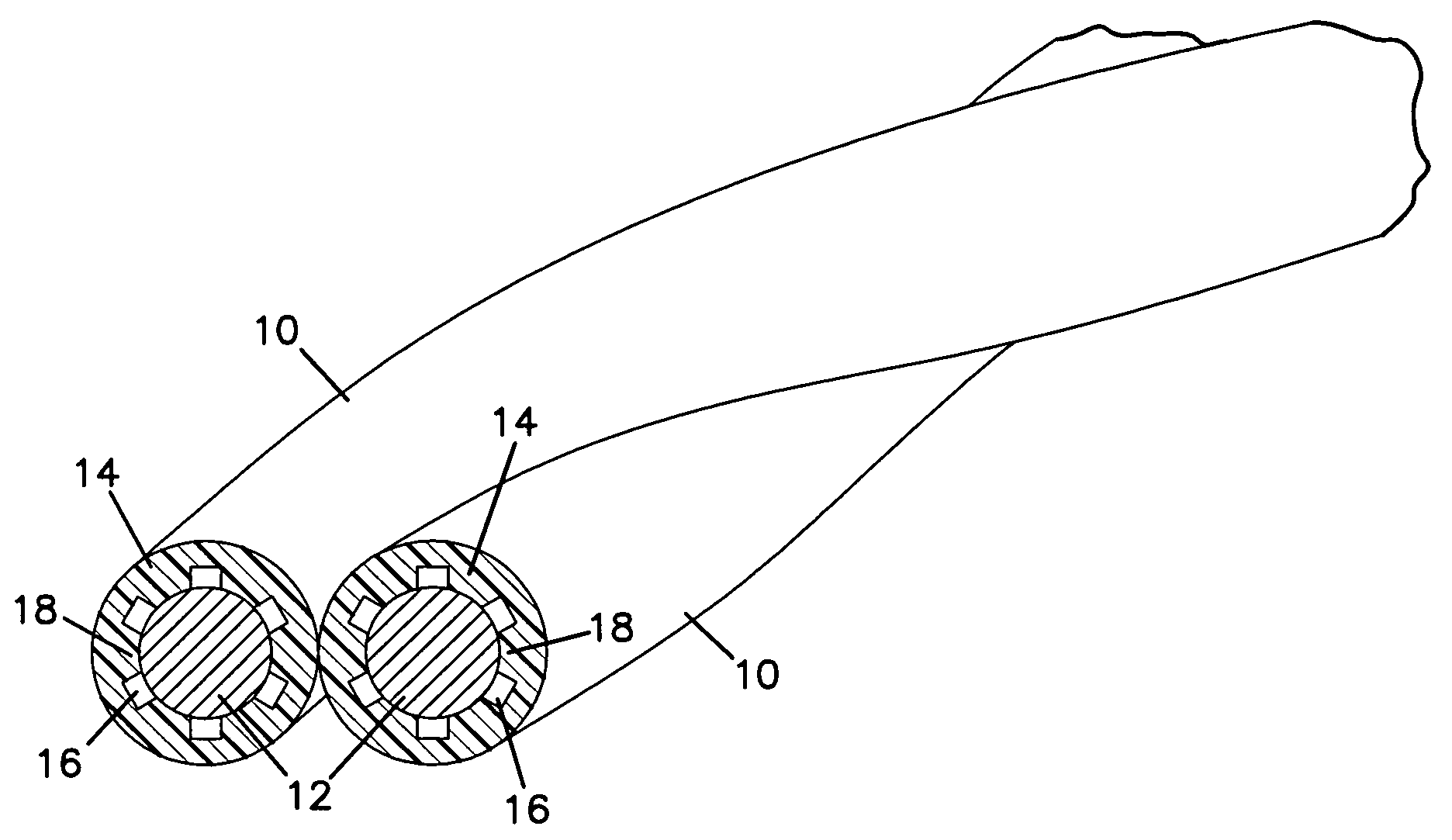
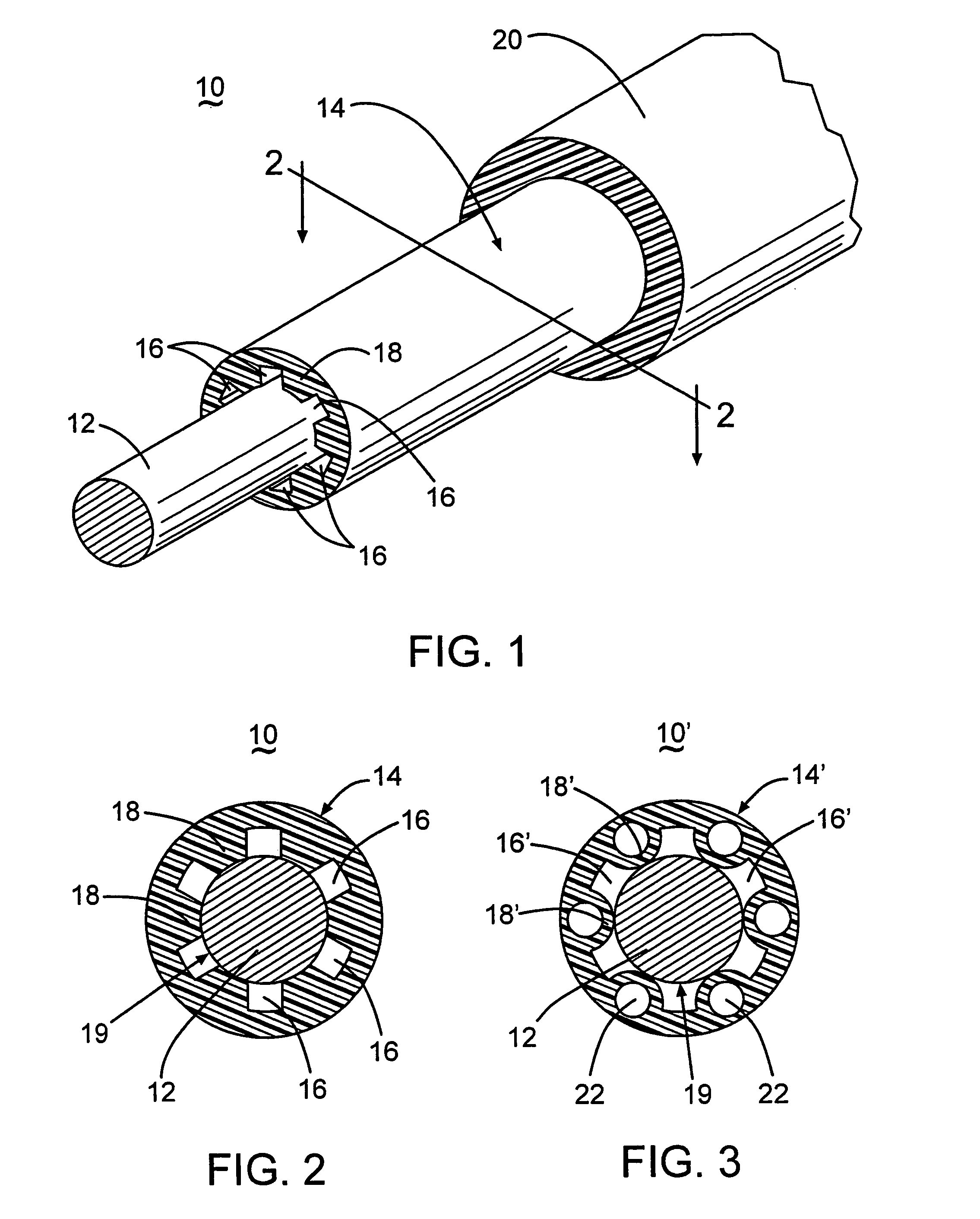
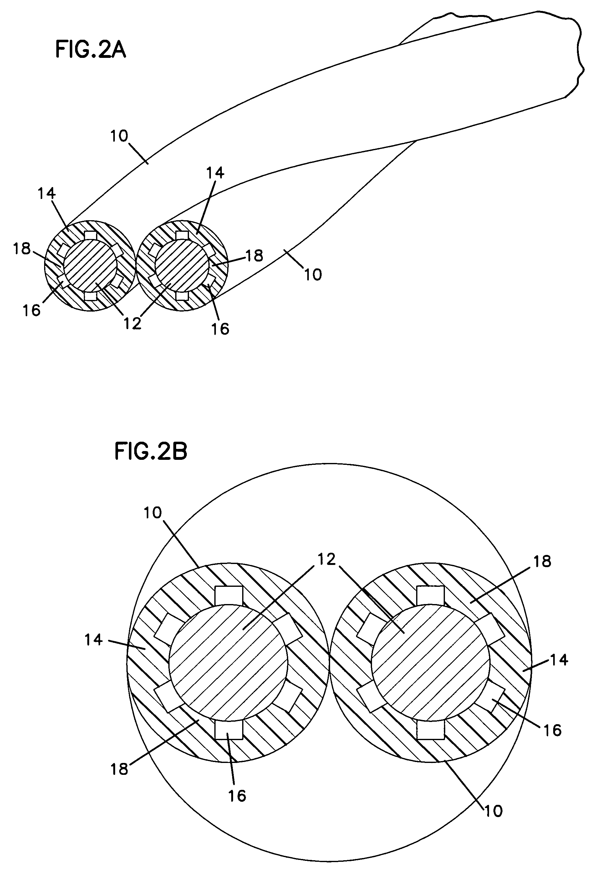
[0026]A wire 10 of the present invention has a conductor 12 surrounded by a primary insulation 14, as shown in FIG. 1. Insulation 14 includes at least one channel 16 that runs the length of the conductor. Multiple channels may be circumferentially disposed about conductor 12. The multiple channels are separated from each other by legs 18 of insulation. The individual wires 10 may be twisted together to form a twisted pair, as shown in FIGS. 2A and 2B. Twisted pairs, in turn, may be twisted together to form a multi-pair cable. Any plural number...


PUM

PropertyMeasurementUnit
thickaaaaaaaaaa
dielectric constantaaaaaaaaaa
diameteraaaaaaaaaa

Abstract

The present invention relates to an improved isolated core or insulated conductor with a low dielectric constant and reduced materials costs. Apparatuses and methods of manufacturing the improved isolated core or insulated conductor are also disclosed. Twisted wire pairs having first and second wires, each of the first and second wires including a conductor and polymeric insulator surrounding the conductor are also disclosed. The polymeric insulators have channels that run along the length of the conductor. The conductors have exterior surfaces exposed to gas within the channels.

Description

CROSS-REFERENCE TO RELATED APPLICATIONS[0001]This application is a Continuation of U.S. application Ser. No. 10 / 790,583, filed Mar. 1, 2004, which is a Continuation of U.S. application Ser. No. 10 / 389,254, filed Mar. 14, 2003, which is a Continuation-In-Part of U.S. application Ser. No. 10 / 321,296, filed Dec. 16, 2002, now U.S. Pat. No. 6,743,983, which in turn is a Continuation-In-Part of U.S. application Ser. No. 10 / 253,212, filed Sep. 24, 2002, now abandoned the entire teaching of these applications being incorporated herein by this reference.FIELD OF THE INVENTION[0002]The present invention relates to an improved wire and methods of making the same.BACKGROUND OF THE INVENTION[0003]One method of transmitting data and other signals is by using twisted pairs. A twisted pair includes at least one pair of insulated conductors twisted about one another to form a two conductor pair. A number of methods known in the art may be employed to arrange and configure the twisted pairs into var...

Claims


Application Information

Patent Timeline
Patent Type & Authority Patents(United States)
IPC IPC(8): H02G15/00H01B7/02H01B11/00
CPCH01B7/0233H01B11/002H01B7/0275H01B11/12H01B7/0216H01B7/04
Inventor WIEKHORST, DAVIDSTUTZMAN, SPRINGSTUTZMAN, JEFFJUENGST, SCOTTJOHNSTON, FREDDICKMAN, JIM L.KENNY, ROBERT
Owner COMMSCOPE TECH LLC
Why Eureka
Try Eureka