Fluid cooled electric machine

Inactive Publication Date: 2006-05-23
COMPACT DYNAMICS
View PDF12 Cites 20 Cited by
  • Summary
  • Abstract
  • Description
  • Claims
  • Application Information

AI Technical Summary

Benefits of technology

[0013]The object of the invention is therefore to provide electrical machines of the type cited initially which avoid

Problems solved by technology

The problem above all here is the cabling complexity and the electromagnetic screening required due to the lines between the electrical machine and the frequency converter.
The cooling of the power electronics of the frequency converter also requires significant expenditure.
As a further problem it

Method used


Image

  • Fluid cooled electric machine
  • Fluid cooled electric machine

Examples


Example

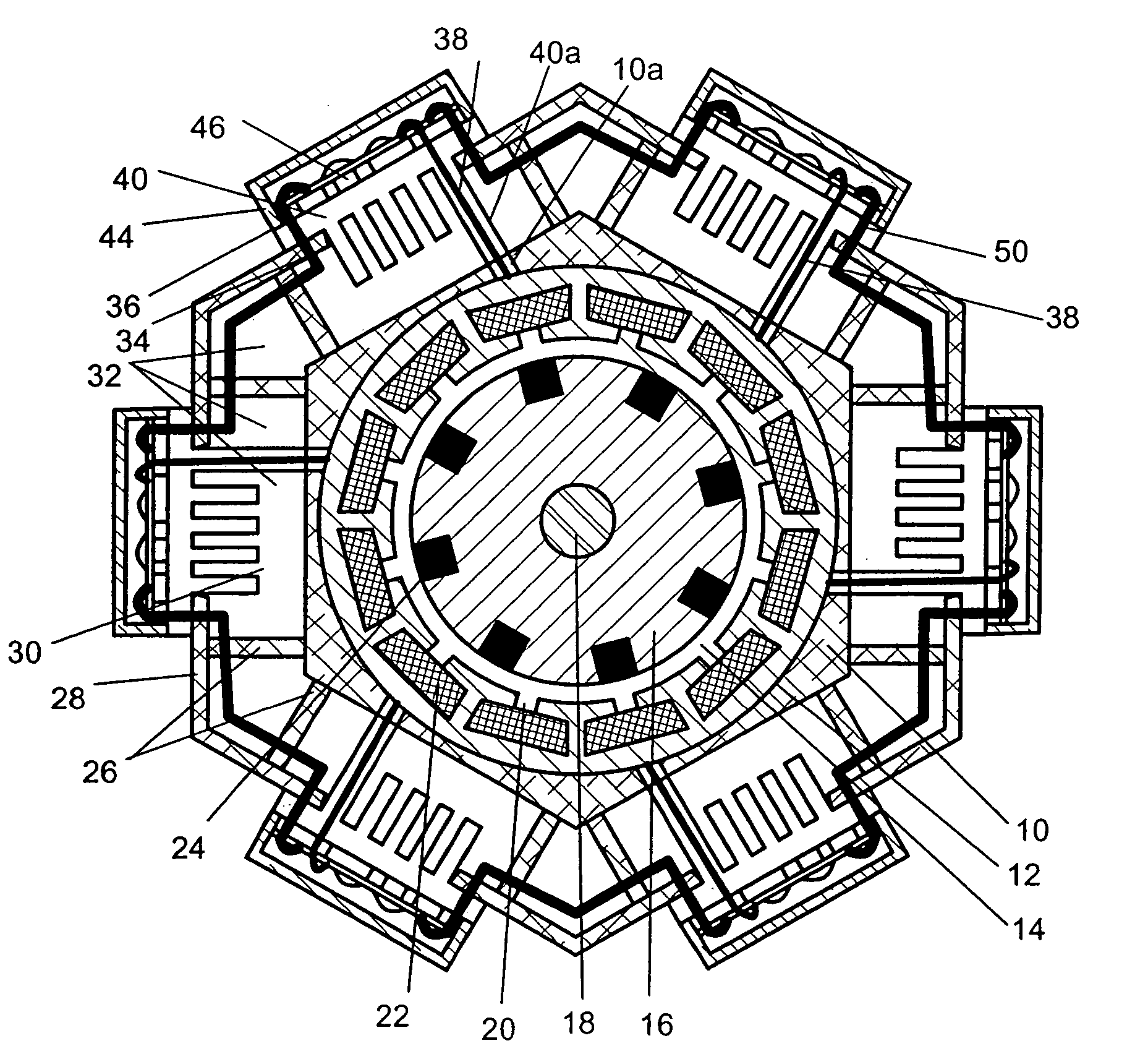
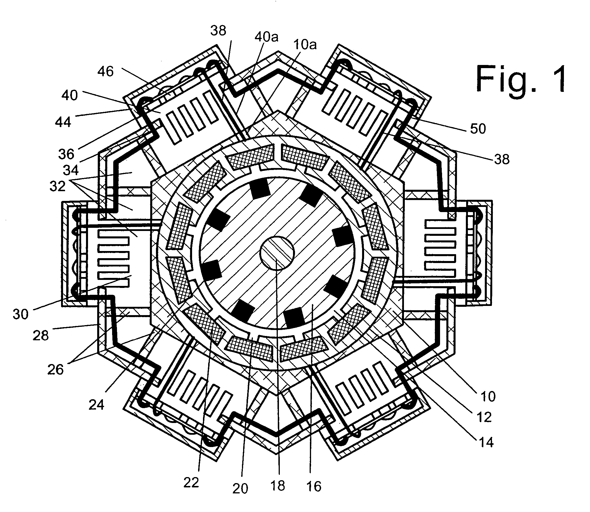
DETAILED DESCRIPTION OF THE DRAWING

[0025]The fluid-cooled electrical machine shown in FIG. 1 is a rotary field machine formed as an internal rotor machine. This machine has a housing 10 in which are arranged a stator 12 and, separated by an air gap 14, a rotor 16 with a shaft 18. The stator 12 is formed by plates stacked above each other and has grooves 20 open towards the inner periphery surface to hold stator coils 22 merely indicated.

[0026]The rotor 16 is also formed by plates stacked above each other and along its outer periphery has, evenly distributed and coaxially to the shaft 18, rods 24 of a short-circuit cage.

[0027]The housing 10 has on its outside substantially radial webs 26 which together with the outside of the housing 10 and a casing 28 form a cooling device 30. This cooling device 30 has cooling channels 32 oriented coaxially to the shaft 18. The electric machine or its stator 12 is thermally coupled via the outside of the housing 10 with the cooling channels 32 of t...


PUM


Abstract

The invention concerns a fluid-cooled electrical machine with a housing in which are arranged a stator and a rotor with stator and/or rotor coils, wherein the electrical machine is coupled heat-conductively with a cooling device arranged on its periphery and connected with an electronic power control. The electronic power control is divided into several modules, each of which are electrically connected with at least one of the stator and/or rotor coils, wherein the modules are arranged distributed on the periphery of the electrical machine and coupled heat-conductively with the cooling device.

Description

BACKGROUND TO THE INVENTION[0001]The invention concerns a fluid-cooled electrical machine with a housing in which are arranged a stator and a rotor with stator and / or rotor coils, wherein the electrical machine is coupled heat-conductively with a cooling device arranged on its periphery, and is connected with an electronic power control. Fluid-cooled machines, depending on area of application, are cooled with either oil or water, wherein the fluid is transported by a pump activated either by the electrical machine itself or by a separate drive.DEFINITION OF TERMS[0002]The term “electrical machine” here means an electrical rotating machine in the form of an internal or external rotor machine. An electrical machine can be both an electric motor and an electrical generator. The invention applies in particular to rotating machines of all types (synchronous, asynchronous and reluctance machines, permanently excited machines or similar).PRIOR ART[0003]In the prior art, it is known to oper...

Claims


Application Information

Patent Timeline
IPC IPC(8): H02K9/00H02K5/20H02K9/19H02K11/04
CPCH02K5/20H02K11/048H02K9/19H02K5/203H02K11/05H02K11/33H02K2213/12H02K9/22H05K7/20927
Inventor GRUNDL, ANDREASHOFFMANN, BERNHARD
Owner COMPACT DYNAMICS
Why Eureka
Try Eureka